
Bolt for vacuum apparatus

A vacuum device and screw technology, applied in the direction of screws, threaded fasteners, connecting components, etc., can solve problems such as affecting vacuum acquisition and small gaps

Inactive Publication Date: 2007-04-25
INST OF ELECTRICAL ENG CHINESE ACAD OF SCI
View PDF0 Cites 3 Cited by
  • Summary
  • Abstract
  • Description
  • Claims
  • Application Information

AI Technical Summary

Problems solved by technology

[0002] When various screws are used in vacuum devices, since there is a gap between the threads and between the screw and the screw hole, and the gap is not large, if the screw hole is not transparent, the gas in the gap is not easy to be sucked away, so Become a source of outgassing in the vacuum chamber, affecting the acquisition of vacuum

Method used


Image

  • Bolt for vacuum apparatus

Examples


Embodiment Construction

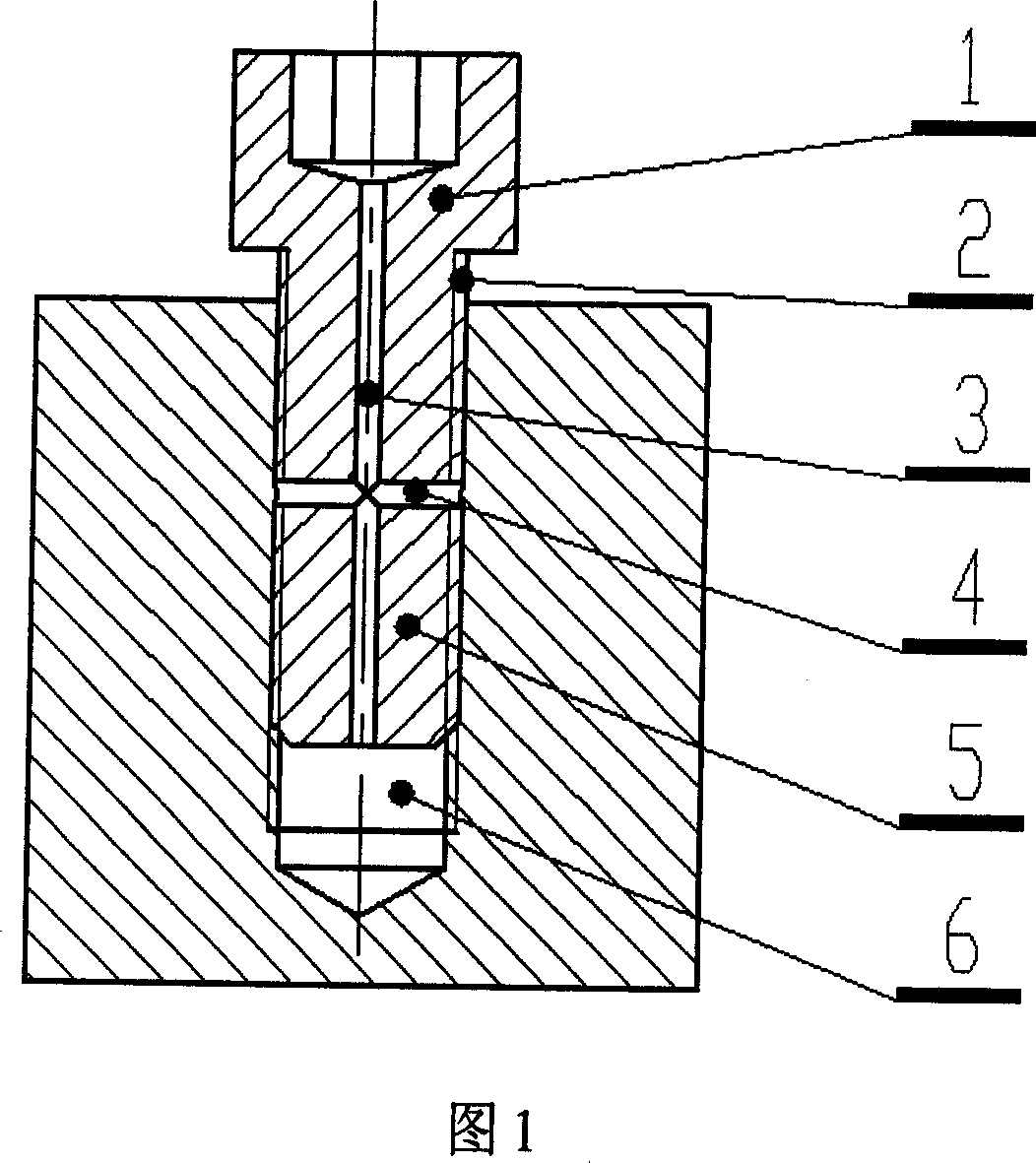
[0007] The present invention will be further described below in conjunction with the accompanying drawings and specific embodiments. The screw of the present invention consists of a nail head 01 and a nail body 05. The outer edge surface of the nail body 05 is provided with an external thread 02, and a through hole 03 is opened in the axial direction of the nail body 05, and a through hole 04 is opened in a direction perpendicular to the outer edge surface of the nail body 05. The axial through hole 03 facilitates the removal of gas in the space between the screw and the head of the screw hole 06, and the vertical through hole 04 facilitates the removal of gas between the screw and the thread on the outer edge of the screw hole, thereby contributing to the vacuum of the vacuum device.


PUM


Abstract

The invention relates a bolt for vacuum equipment, comprising bolt head [01] and bolt body [05]. Outer thread [02] is set on the outer edge face of bolt body [05], one via hole [03] is opened in the bolt body [02] along the axial direction and one via hole [04] is set along the vertical direction with outer edge face of bolt body [05]. Axial air in the top between bolt and screw is removed conveniently by the axial via hole [03] and air between bolt and screw thread on the outer edge face of bolt is removed conveniently so as to help to obtain vacuum of vacuum equipment.

Description

technical field [0001] The invention relates to a screw for a vacuum device. Background technique [0002] When various screws are used in vacuum devices, since there is a gap between the threads and between the screw and the screw hole, and the gap is not large, if the screw hole is not transparent, the gas in the gap is not easy to be sucked away, so Become a source of outgassing in the vacuum chamber, affecting the acquisition of vacuum. Contents of the invention [0003] The purpose of this invention is to overcome the defective of prior art, propose a kind of screw of new structure. The invention helps to eliminate the gas between the screw threads and between the screw and the screw hole, and avoids becoming a gas release source in the vacuum chamber, which affects the obtaining of vacuum. [0004] Screw of the present invention is made up of nail body and nail head, and its structural feature is as follows: [0005] The outer edge of the nail is provided with an ...

Claims


Application Information

Patent Timeline
Patent Type & Authority Applications(China)
IPC IPC(8): F16B35/00
Inventor 初明璋韩立
Owner INST OF ELECTRICAL ENG CHINESE ACAD OF SCI
Learn More