Firing target automatic score apparatus

A shooting target, automatic technology, applied in the direction of target, target indication system, attack equipment, etc., to achieve the effect of low cost and high practicability

Inactive Publication Date: 2007-05-02
揭雪强
View PDF0 Cites 8 Cited by
  • Summary
  • Abstract
  • Description
  • Claims
  • Application Information

AI Technical Summary

Problems solved by technology

[0003] In order to change the current situation where manual target reporting is still widely used, the present invention provides an automatic scoring device for shootin

Method used


Image

  • Firing target automatic score apparatus
  • Firing target automatic score apparatus

Examples


Embodiment Construction

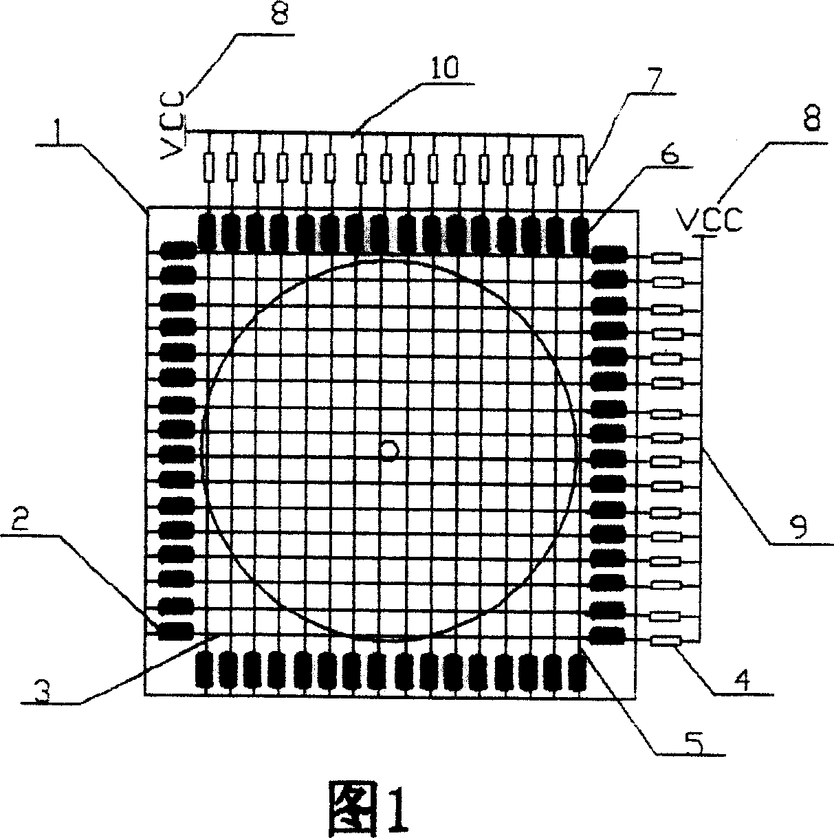
[0013] In the figure, the horizontal target rod array is formed by a number of horizontal target rods arranged in parallel. The horizontal target rod is composed of a steel wire (3), two springs (2), and a resistor (4). Both ends of the steel wire are automatically scored by a spring and a shooting target. The device frame (1) is fixed, one end of the steel wire is connected to VCC (8) through a resistor, and the other end of the steel wire is connected to an input and output port of the control module (11) of the shooting target automatic scoring device control module (11) through a wire; the vertical target rod array is arranged in parallel by several vertical target rods The vertical target rod is composed of a section of steel wire (5), two sections of spring (6) and a resistor (7). The two ends of the steel wire are fixed by a section of spring and the frame (1) of the automatic scoring device for shooting targets, and one end of the steel wire is connected to VCC through a...


PUM


Abstract

An automatic point-recording device of shooting target consist of frame of automatic point-recording device, horizontal target array, vertical target array, control module, radio emission module, radio receiving module and display. It is feature as utilizing two said target arrays to form a grid, setting grid size to be less than diameter of bullet to let bullet contact with steel wire of grid when grid is hit by bullet in order to obtain coordinate of hitting point then to obtain ring number of the shoot.

Description

Technical field [0001] The invention relates to an automatic scoring device for shooting targets. Background technique [0002] Live ammunition shooting requires target reporting to verify the effect of shooting. And also widely use artificial target report at present, cause error easily like this, also more dangerous, also can't carry out systematic and effective management simultaneously, to improve the shooting technique of shooter. Contents of the invention [0003] In order to change the current situation that manual target reporting is widely used at present, the present invention provides an automatic scoring device for shooting targets, which has simple mechanism, low cost and reliable scoring, and can be widely used in shooting training to improve the shooting skills of shooting personnel. [0004] The technical scheme adopted by the present invention to solve its technical problems is: the present invention is composed of a shooting target automatic scoring devi...

Claims


Application Information

Patent Timeline
IPC IPC(8): F41J5/044
Inventor 揭雪强
Owner 揭雪强
Why Eureka
Try Eureka