Forming stripper, and method

A demoulding device and demoulding technology, applied in the field of demoulding devices, can solve problems affecting the effective area of ​​finished products, complicated mechanisms, complicated processes, etc.

Inactive Publication Date: 2007-05-09
IND TECH RES INST
View PDF4 Cites 8 Cited by
  • Summary
  • Abstract
  • Description
  • Claims
  • Application Information

AI Technical Summary

Problems solved by technology

[0005] At present, there are many known patents aimed at overcoming the above-mentioned vacuum effect, such as a demoulding device and method described in U.S. Patent No. 6416311B1, which uses an external air source to penetrate the mold and pour it into the mold and the molding material. In order to remove the vacuum for demoulding, this method must first form a penetration hole on the mold for external gas injection, and match the position of the gas injection on the device, so the design of the microstructure pattern of the mold is limited and affects the effective area of ​​the finished product
[0006] Another example is the demoulding method described in U.S. Patent No. 5,358,672. During the molding process, an extension tape is placed outside the edge of the mold and pressed together with the molding material. When demolding, the extension tape and the mold are directly pulled up. To separate the mold from the molding material, the use of extended tape in this method will reduce the effective molding area, and even affect the molding quality of the extended tape and its surroundings
[0007] In addition, as the device described in Japanese Patent No. 2004066671, it uses a pneumatic cylinder to cooperate with multiple groups of springs with different functions to bear against the outer edge shoulder of the forming substrate. The mold is separated from the molding material, but this mechanism is complicated and not suitable for nano transfer printing where the mold and the substrate are of the same geometric size
[0008] Another example is the method described in Japanese Patent No. 06270170, which uses a shape memory alloy component to be installed at the edge of the mold. Borrowing a stopper against the base plate to lift the mold to completely disengage it. However, this method requires a special shape memory alloy component to match the difference in temperature changes and the design of the stopper. The process is more complicated.
[0009] It can be seen from the content of the above-mentioned previous patents that most of the technical means for destroying the adsorption force between the mold and the molding material due to the vacuum effect start from the edge of the mold or the molding substrate. However, the technical means used must cooperate with complicated Design or special materials can achieve the purpose, or the transfer area or molding quality will be affected by the setting of the demoulding device

Method used


Image

  • Forming stripper, and method
  • Forming stripper, and method
  • Forming stripper, and method

Examples


Embodiment Construction

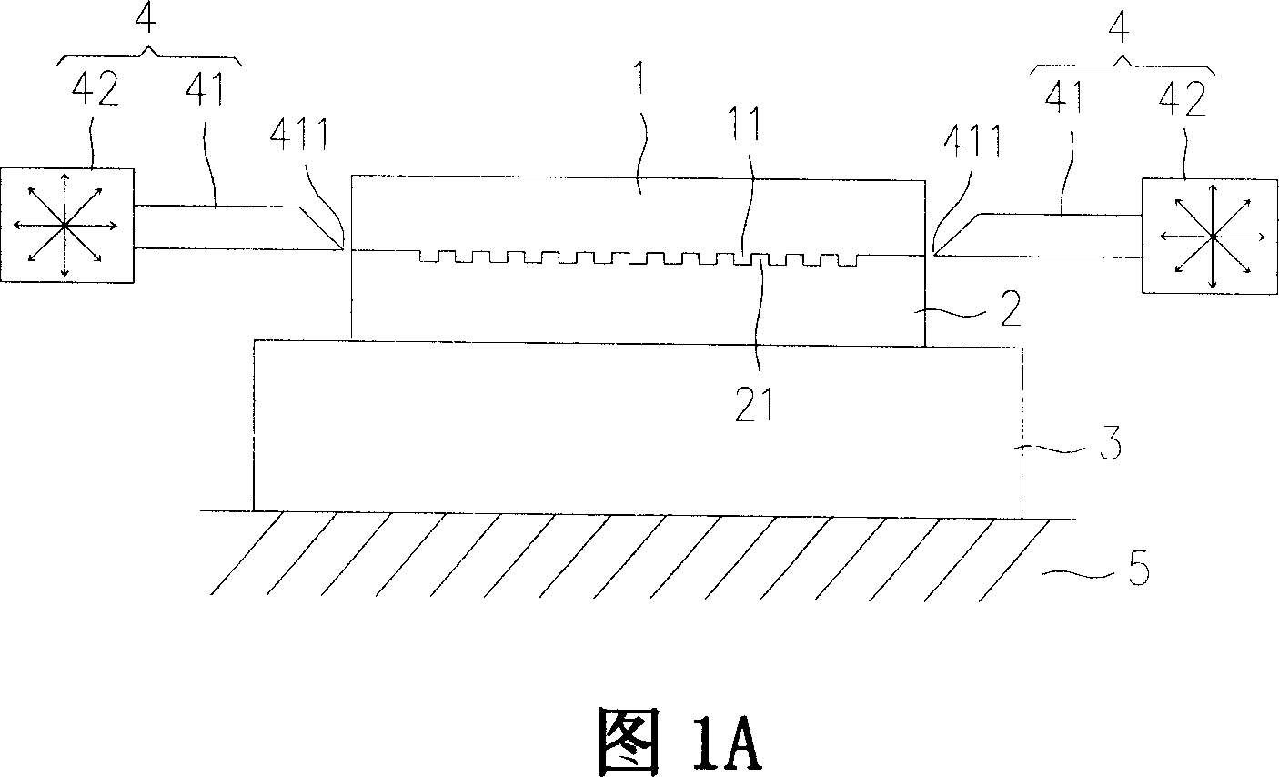
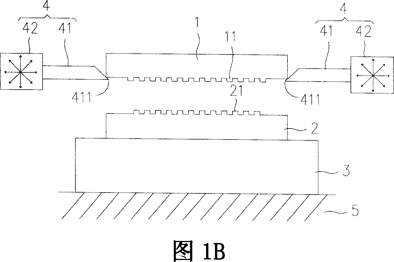
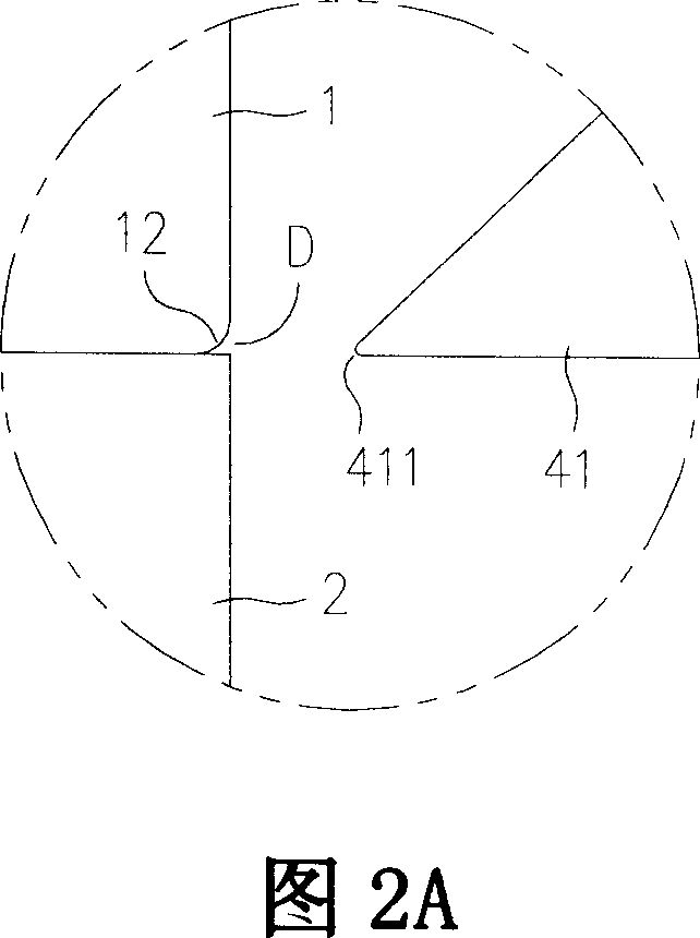
[0030] The technical means and functions used to achieve the purpose of the present invention will be described below with reference to the accompanying drawings, and the embodiments listed in the following figures are only for auxiliary illustration, and the technical means of the present invention are not limited to the listed figures.

[0031] Please refer to the first preferred embodiment of the demoulding device provided by the present invention shown in Fig. 1A and Fig. 1B, which mainly includes a mold 1, a base plate 2, a carrier plate 3 and at least one set of thimble modules 4, wherein the The surface of the mold 1 is provided with a transfer pattern 11. When applied to nano transfer printing technology, the transfer pattern 11 is a micro-nano structure with a characteristic size below 100 μm; the substrate 2 is used for pressing the transfer pattern 11 of the mold 1. Printed on its surface to form a pattern 21, when applied to nano transfer printing technology, the ma...


PUM

PropertyMeasurementUnit
sizeaaaaaaaaaa

Abstract

A demoulding device and method features that at least one pin driving module is used to insert a pin between a mould and a baseplate which has been transfer-printed and moulded to generate a gap between them for eliminating the vacuum effect and said baseplate is further separated from said mould by the pin.

Description

technical field [0001] The invention relates to a demoulding device and method, in particular to a demoulding device and method which have a simple structure and can smoothly separate a mold from a base plate with a slight force. Background technique [0002] In response to the development trend of light, thin, short, and small products, many sophisticated and miniaturized manufacturing technologies have emerged one after another. The evolution of the overall manufacturing technology is from top-down (Top-down) and bottom-up (Bottom-up) -up) manufacturing technologies have intersected at the nanoscale (below 100 μm), and there are many types of nano-manufacturing technologies, but most of them are too slow in processing speed and expensive in required equipment, which is not conducive to mass production. [0003] In terms of nanoimprint technology (Nanoimprint), it mainly uses mechanical force to transfer the micro-nano structure on the mold to the molding material in the sa...

Claims


Application Information

Patent Timeline
Patent Type & Authority Applications(China)
IPC IPC(8): B29C59/02B29C33/46B29C33/42
Inventor 何侑伦巫震华王维汉陈守仁陈来胜
Owner IND TECH RES INST
Why Eureka
Try Eureka