Chain transmission

a chain transmission and chain technology, applied in the direction of driving chains, gearing, hoisting equipment, etc., can solve the problems of affecting the smooth transmission of power, generating significant noise, and generating vibration noise, so as to achieve low noise operation, suppress vibration noise and impact noise, and reduce noise.

Inactive Publication Date: 2009-12-22
TSUBAKIMOTO CHAIN CO
View PDF23 Cites 7 Cited by
  • Summary
  • Abstract
  • Description
  • Claims
  • Application Information

AI Technical Summary

Benefits of technology

[0008]In the operation of the chain transmission having the above-described features, as the chain approaches the rotating sprocket, a roller (or bushing in the case of a bushing chain) moves from a front tooth surface to a back surface without coming into direct collision with a tooth gap bottom. Thus, the chain transmission of the invention avoids vertical movement the transmission chain due to polygonal movement during engagement of the chain with the sprocket. Consequently changes in the speed of the transmission chain are suppressed, and vibration noise and impact sounds are also suppressed, so that low noise operation can be realized. Furthermore, since the rollers or bushings of the chain become engaged with back tooth surfaces as they travel while in engagement with the sprocket, the rollers or bushings can smoothly disengage the sprocket.

Problems solved by technology

The vertical motion induces chordal vibration in the chain, which, in turn, generates vibration noise.
These impact sounds are responsible for significant amounts of noise generated in the operation of the conventional chain transmission.
The polygonal motion of the chain also causes changes in speed along the direction of travel of the transmission chain, which also impairs smooth transmission of power.

Method used


Image

  • Chain transmission
  • Chain transmission
  • Chain transmission

Examples


Embodiment Construction

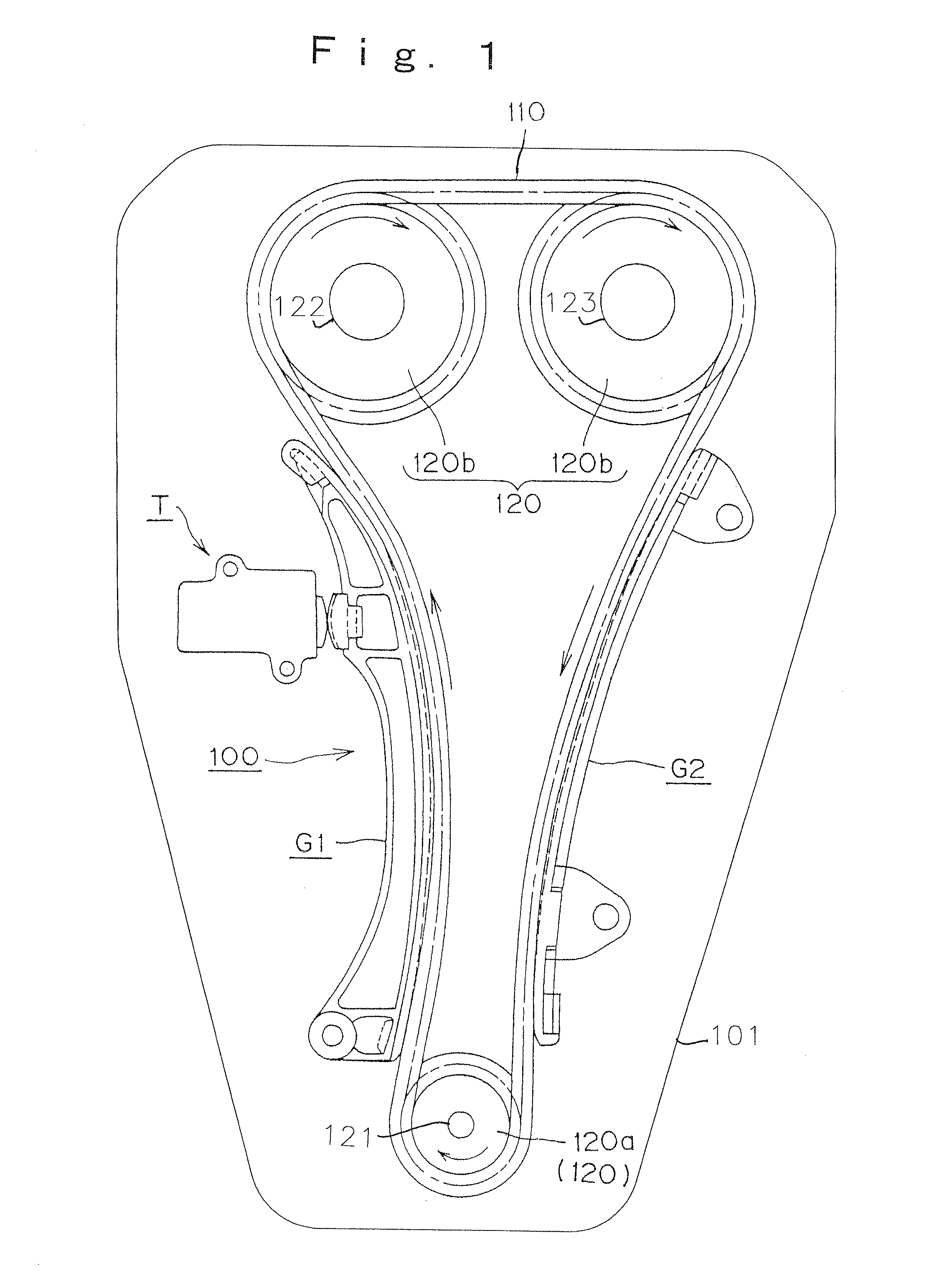
[0021]The chain transmission 100, shown in FIG. 1, is a timing transmission used to operate the intake and exhaust valves of a DOHC vehicle engine 101, and is composed of a roller chain 110, and a set of sprockets 120, including a driving sprocket 120a on the engine crankshaft 121, and two driven sprockets 120b, respectively on an intake valve camshaft 122 and an exhaust valve camshaft 123. As noted previously, although a roller chain is shown, the chain can be a bushing chain, an offset type chain, a seal chain, or the like. A tensioner T controls tension in chain 110 by pressing against the back of a pivoted guide G1 on which the slack side of the chain slides, and the tension side of the chain slides on a fixed guide G2.

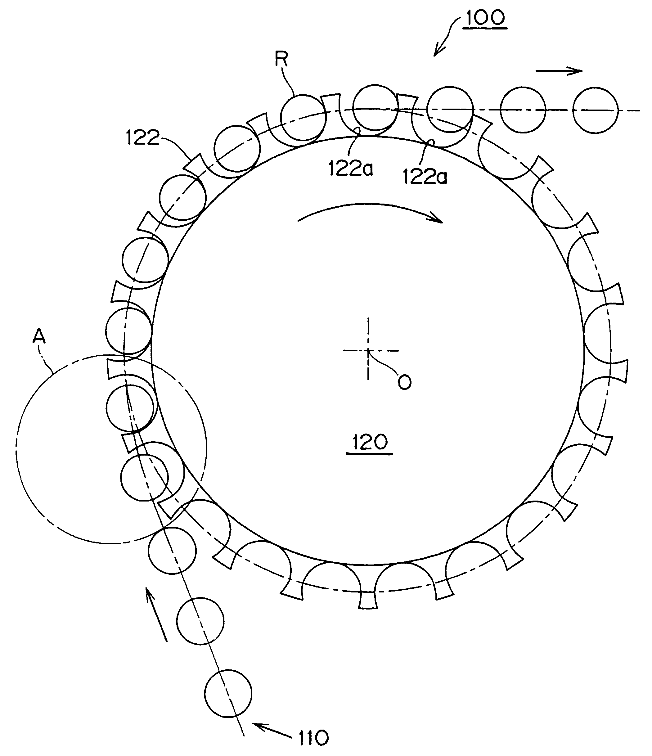
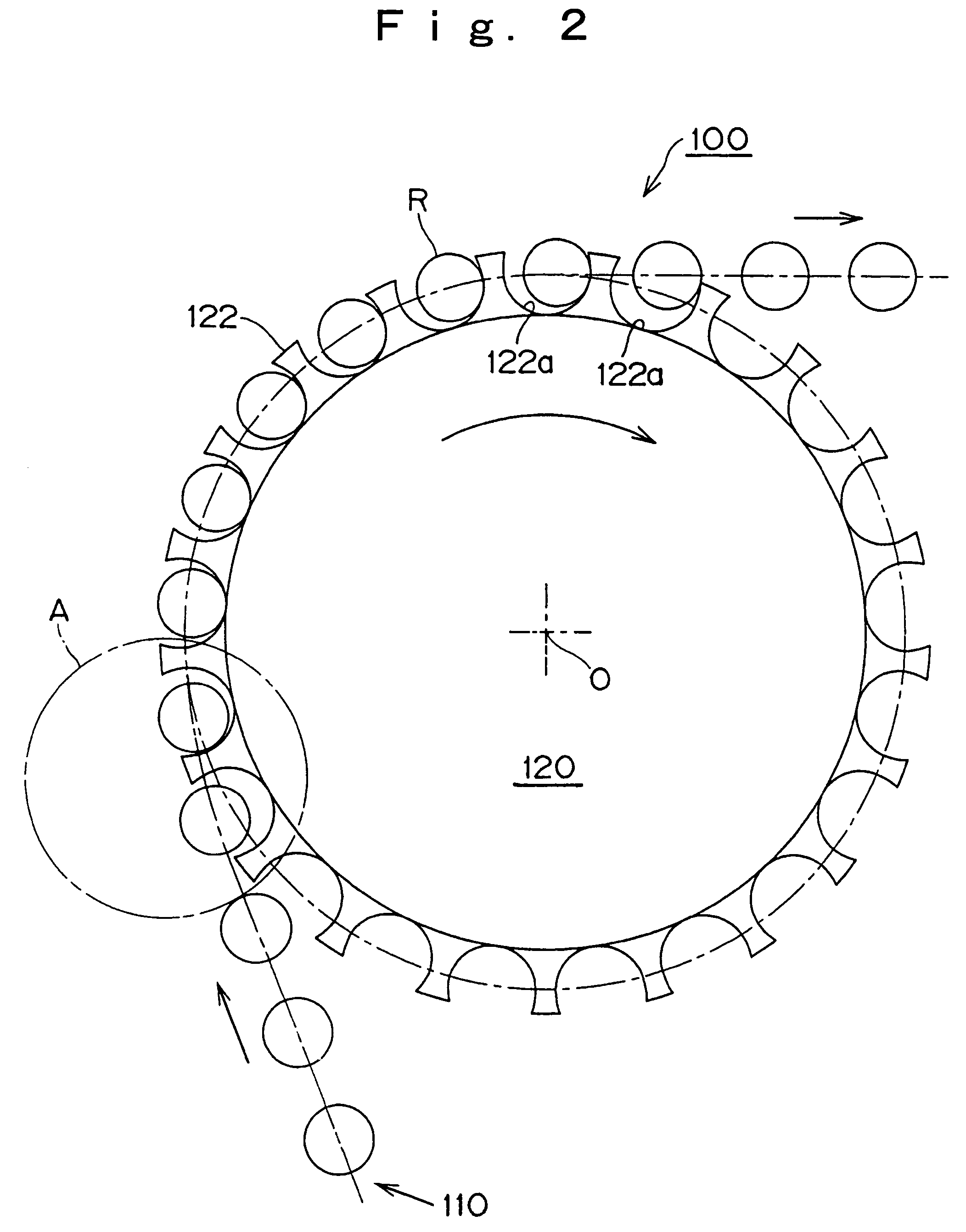
[0022]In the sprocket 120, as shown in FIGS. 2 and 3, sprocket teeth 122 are formed on a sprocket body 121. Each tooth has a front tooth surface 122b, facing in the direction of sprocket rotation, and a back tooth surface 122c facing in the opposite direction. The...


PUM


Abstract

In a chain transmission in which a roller chain transmits power from a driving sprocket to one or more driven sprockets, the sprocket teeth are shaped so that at a location radially outward from the sprocket pitch circle, the distance between the front surface of each sprocket tooth to a radial reference line from the sprocket center through the center of the tooth root, is at least as great as the distance from the centerline to the front tooth surface at the pitch circle. The tooth faces merge smoothly with the tooth gap bottom, the sprocket root diameter is smaller than the root diameter according to ISO standards, and the radius of the arcuate tooth gap bottom is greater than the radius of the chain roller.

Description

CROSS REFERENCE TO RELATED APPLICATION[0001]This application claims priority on the basis of Japanese patent application 2004-335983, filed on Nov. 19, 2004. The disclosure of Japanese patent application 2004-335983 is hereby incorporated by reference.FIELD OF THE INVENTION[0002]This invention relates to a chain transmission used in an internal combustion engine such as a vehicle engine, and relates specifically to a chain transmission in which vertical motion of the chain, due to polygonal movement as it engages a sprocket, is suppressed.BACKGROUND OF THE INVENTION[0003]FIG. 8 shows a conventional chain transmission 500, in which a transmission chain 510 is engaged with a sprocket 520, having a tooth form as defined in ISO 606:1994(E). This chain transmission is described in U.S. Pat. No. 5,427,582. As shown in FIG. 9, in the conventional chain transmission 500, as the chain rollers R engage a sprocket, they contact the bottoms 522a of the gaps between sprocket teeth 522. As a resu...

Claims


Application Information

Patent Timeline
Patent Type & Authority Patents(United States)
IPC IPC(8): F16H7/06F16H55/30
CPCF16H7/06F16H55/30F16H55/08
Inventor KUBO, AIZOHISHIDA, HIROKISONODA, MASATOSHI
Owner TSUBAKIMOTO CHAIN CO
Why Eureka
Try Eureka