Concrete inspection well molding mould with base

A technology for forming molds and concrete, applied in the direction of molds, ceramic molding cores, etc., can solve the problems of poor fluidity of dry hard concrete, inability to guarantee the compactness of the bottom of the product, and low final yield, and achieve high mold utilization and stable structure , The effect of product quality improvement

Active Publication Date: 2015-07-01
苏州科星混凝土水泥制品装备有限公司
View PDF5 Cites 8 Cited by
  • Summary
  • Abstract
  • Description
  • Claims
  • Application Information

AI Technical Summary

Problems solved by technology

In this method, one way is: when pouring the concrete material, the inner mold with the bottom is placed with the bottom down and the mouth up. This way, due to the poor fluidity of the dry hard concrete, the bottom density of the produced product will be lower. Can not guarantee
Another method is: when adding materials, the mold is placed with the bottom facing up and the mouth facing down. Although this method solves the problem of the compactness of the bottom of the product, when demoulding in this way in the prior art, the inner mold is first Separate from the concrete product and the outer mold, that is, remove the inner mold first, and then let the concrete product be cured in the outer mold for a certain period of time, and then separate the outer mold from the concrete product. During the maintenance, the base of the cylindrical product faces upwards, The center of gravity of the whole product is on the upper side. Since the concrete has not been completely solidified at this time, the strength has not been fully established, and the structure is unstable. In the process, due to the same reason, the product is also very prone to damage); in addition, because the outer mold and the inner mold need to be separated from the concrete product for a period of time, the demoulding time is long, the production efficiency is low, and the outer mold is removed. In the process, the product is often damaged because there is no internal mold support that has been removed. In order to solve this problem, more auxiliary equipment needs to be added. Not only is the process complicated, but the final yield is low and the product quality is low. higher production costs

Method used


Image

  • Concrete inspection well molding mould with base
  • Concrete inspection well molding mould with base
  • Concrete inspection well molding mould with base

Examples


Embodiment Construction

[0026] The present invention will be described in further detail below in conjunction with the accompanying drawings and specific embodiments.

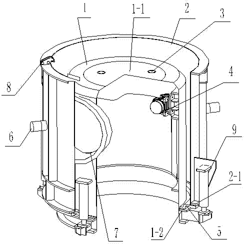
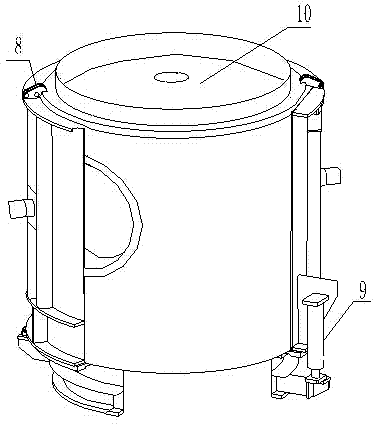
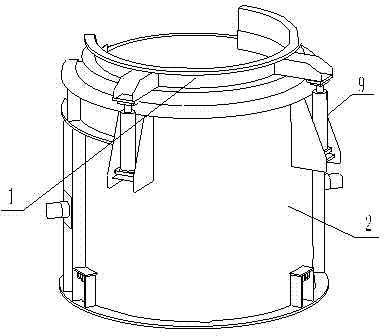
[0027] As shown in the figure, a concrete inspection well forming mold with a base includes a cylindrical shape (the cylindrical shape described herein includes a cylindrical shape, an elliptical cylindrical shape, and a polygonal cylindrical shape, such as a triangular cylindrical shape, a quadrangular cylindrical shape, and a five-sided cylindrical shape. Cylindrical, etc.) inner mold 1 and outer mold 2, one end of the inner mold 1 has a bottom 1-1, and one end of the outer mold 2 is provided with an annular socket plate 5, and the socket plate 5 is connected with the outer mold at the end of the outer mold. The mold flange 2-1 is fixedly connected. The inner diameter of the socket plate 5 is installed in cooperation with the outer diameter of the lower end of the inner mold, and the corresponding position on the outer wall of the i...


PUM


Abstract

The invention provides a concrete inspection well molding mould with a base. The concrete inspection well molding mould comprises a cylindrical inner die and an outer die; one end of the inner die is provided with a bottom part, and an inspection well molding space forms between the inner die and the outer die; a faucet disk used for supporting concrete material filled in the molding space is arranged between one end of the inner die without the bottom part and corresponding end of the outer die; the faucet disk is fixedly connected with the inner die or the outer die, and one end of the inner die without the bottom part is connected with the outer die through a jacking mechanism. The concrete inspection well molding mould further comprises a bottom tray for pressing the concrete material filled in the molding space and a locking mechanism used for locking the bottom tray on the mould. By adopting the concrete inspection well molding mould, the molding efficiency and production quality of the inspection well are obviously improved.

Description

technical field [0001] The invention relates to the technical field of concrete product forming, in particular to a concrete inspection well forming mold with a base. Background technique [0002] In the current prior art, the production method of the concrete cylindrical product with the base has two kinds of pouring forming production method and vibration forming production method. [0003] The above two production methods both adopt a forming mold comprising a cylindrical inner mold and an outer mold, and a concrete product molding space is formed between the inner mold and the outer mold. [0004] The vibration forming production method is: inject dry hard concrete into the forming mold, and demould immediately after vibration compaction. In this method, one way is: when pouring the concrete material, the inner mold with the bottom is placed with the bottom down and the mouth up. This way, due to the poor fluidity of the dry hard concrete, the bottom density of the prod...

Claims


Application Information

Patent Timeline
Patent Type & Authority Applications(China)
IPC IPC(8): B28B21/82
CPCB28B21/82B28B21/86
Inventor 褚建中胡锦锋
Owner 苏州科星混凝土水泥制品装备有限公司
Why Eureka
Try Eureka