Lead frame jumper wire combination device
A combination device and lead frame technology, applied in the direction of transportation and packaging, conveyor objects, electrical components, etc., can solve the problems of reduced production efficiency, operator fatigue, low combination efficiency, etc., to improve production efficiency, improve combination accuracy, The effect of improving positional accuracy
- Summary
- Abstract
- Description
- Claims
- Application Information
AI Technical Summary
Problems solved by technology
Method used
Image

Examples
specific Embodiment approach
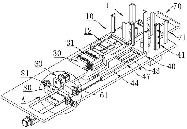
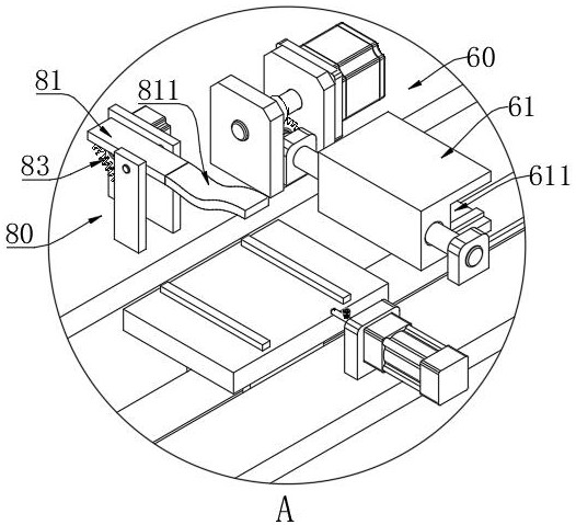
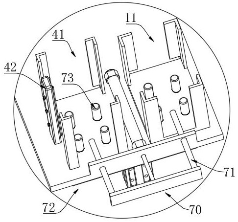
[0064] Specific embodiments: the frame suction cup 20 equipped with the lead frame and the wire jumper suction cup 50 equipped with jumpers move to the first turning mechanism 30 at the same time; until the frame suction cup 20 is located above the rotating rod 31, the jumper wire suction cup 50 is located on the rotating rod 31 and turned over Down after 180°. Then if Figure 16 As shown, the frame suction cup 20 is turned over 180° to the jumper suction cup 50 side by using the first turning mechanism 30, as Figure 18 As shown, after the frame suction cup 20 is combined with the jumper suction cup 50 , the claw 34 is released to separate the rotating rod 31 from the frame suction cup 20 . Then if Figure 19 As shown, the combined frame suction cup 20 and wire jumper suction cup 50 are moved into the U-shaped groove 611 of the rotating block 61 through the transfer plate 43 . later as Figure 20 After the frame suction cup 20 and the wire jumper suction cup 50 are turned...
PUM
 Abstract
Description
Claims
Application Information
 - R&D
- Intellectual Property
- Life Sciences
- Materials
- Tech Scout
- Unparalleled Data Quality
- Higher Quality Content
- 60% Fewer Hallucinations
Browse by: Latest US Patents, China's latest patents, Technical Efficacy Thesaurus, Application Domain, Technology Topic, Popular Technical Reports.
© 2025 PatSnap. All rights reserved.Legal|Privacy policy|Modern Slavery Act Transparency Statement|Sitemap|About US| Contact US: help@patsnap.com