
Sequential switching of relay servers according to server state

A technology of communication control and IP communication, which is applied in the direction of telephone communication, telephone service network, digital transmission system, etc. It can solve the problems of increased load and incapable of terminal point-to-point communication, and achieve the effect of preventing the decline of relay function

Inactive Publication Date: 2007-05-09
KK TOSHIBA
View PDF2 Cites 10 Cited by
  • Summary
  • Abstract
  • Description
  • Claims
  • Application Information

AI Technical Summary

Problems solved by technology

However, signal paths need to be established between the address resolution server and all terminals in advance, and point-to-point communication between terminals cannot be performed
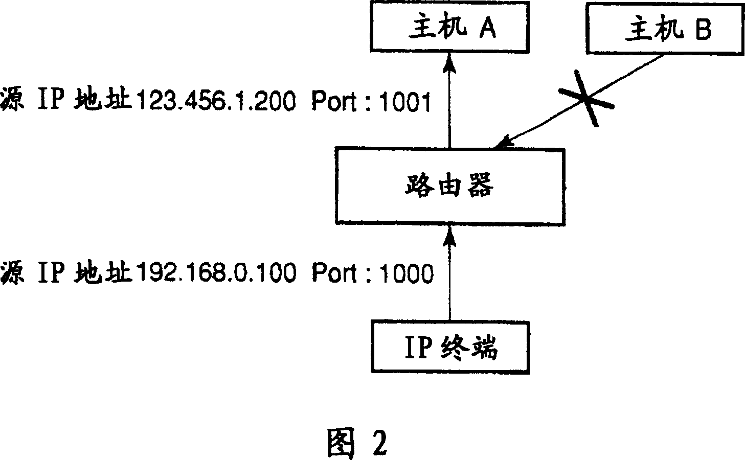
[0009] As described above, when a NAT router is set in a communication system via an IP network, the NAT router may restrict communication between terminals on different networks
To prepare for such situations, a relay server is set up, but the load on this relay server increases with the traffic

Method used


Image

  • Sequential switching of relay servers according to server state
  • Sequential switching of relay servers according to server state
  • Sequential switching of relay servers according to server state

Examples


Embodiment Construction

[0023] Hereinafter, various embodiments according to the present invention will be described with reference to the accompanying drawings.

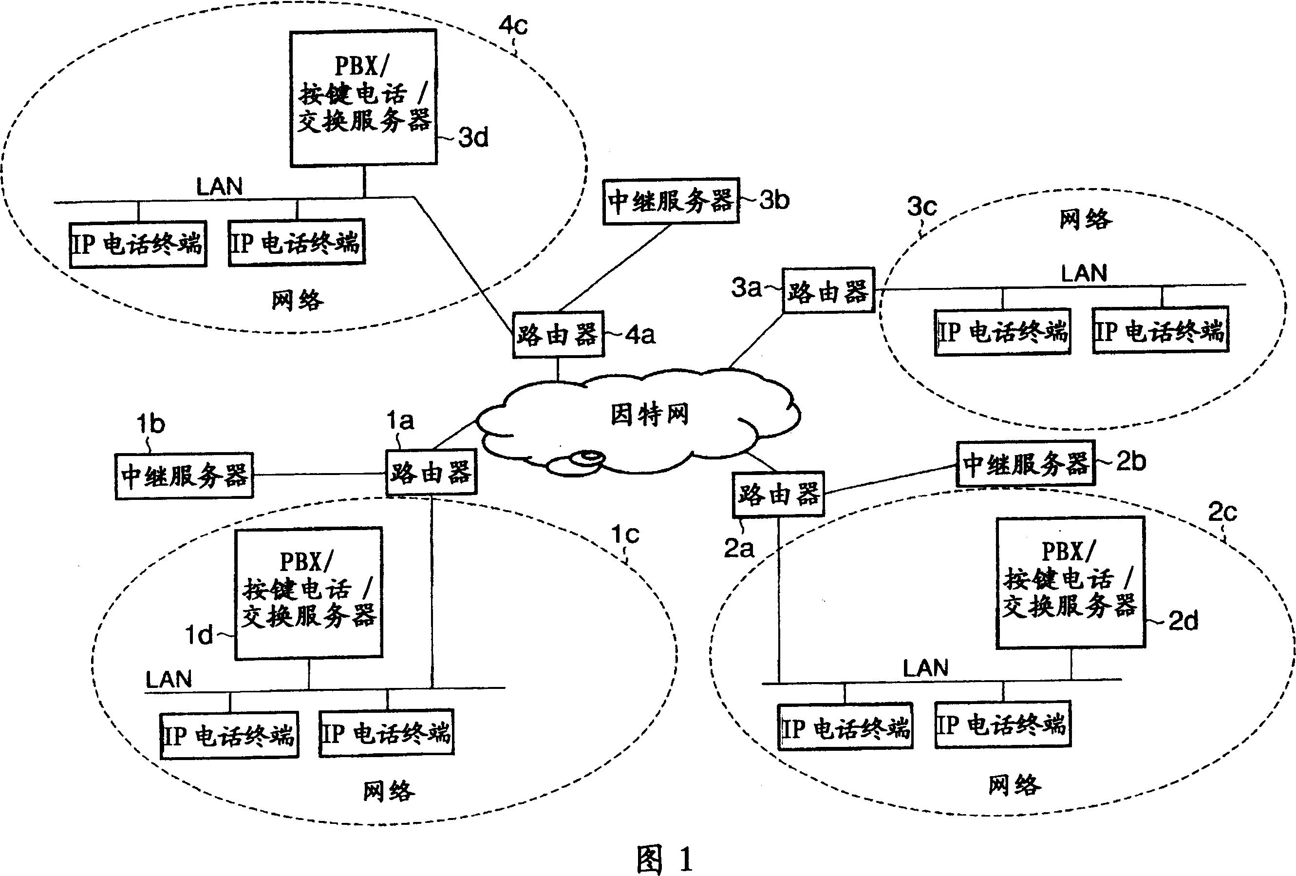
[0024] FIG. 1 is an exemplary block diagram illustrating a communication system according to an embodiment of the present invention. In FIG. 1, mutually different networks 1c, 2c, 3c, and 4c are connected to the Internet through routers 1a, 2a, 3a, and 4a, respectively. The network 1c includes a plurality of IP telephone terminals deployed in a LAN (Local Area Network) and a PBX (Private Branch Exchange) / key phone / exchange server 1d for providing exchange services in IP to these terminals. The network 2c similarly includes a plurality of IP telephone terminals and a PBX / push phone / exchange server 2d deployed in a LAN. The network 3c includes only IP telephone terminals, but these IP telephone terminals perform voice communication using the PBX / key phone / exchange server 1d in the network 1c or the PBX / key phone / exchange server 2d in the ne...


PUM


Abstract

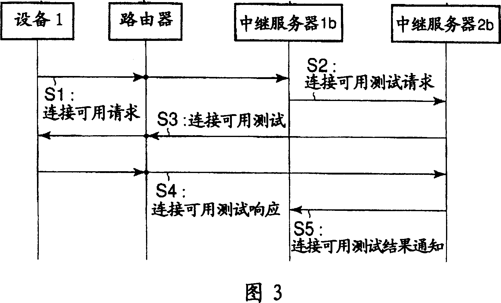
According to one embodiment, a communication control method of a communication system which connects an IP network to plural networks including IP communication devices through routers provided for respective networks, which communicates between the IP communication devices of the different networks through the IP network with IP-packetized data, and which contains plural relay servers including a first and second relay servers, the method includes: determining whether peer-to-peer communication between the IP communication devices can be conducted by using a test packet through the first and second relay servers and the router; relaying the IP packet by the first or second relay server between the IP communication devices determined that the peer-to-peer communication cannot be conducted; and sequentially switching a relay server to relay the IP packet according to a state of the first relay server, from the first relay server to a relay server other than the first relay server.

Description

[0001] Cross References to Related Applications [0002] This application is based on and claims priority from Japanese Patent Application No. 2005-316379 filed on October 31, 2005, the entire contents of which are incorporated herein by reference. technical field [0003] An embodiment of the present invention relates to a communication control method in a communication system that performs information communication through an IP (Internet Protocol) network and includes a router having a conversion function of a private address and a global address. Background technique [0004] In recent years, a system for transmitting IP-packetized data (IP-packetized data) such as voice, video, modem, facsimile, etc. through an IP network has been widely used. In the IP network, a router is a key device. Routers route IP packets based on destination and source addresses. [0005] This type of communication system can be constructed using multiple networks through routers. In such a s...

Claims


Application Information

Patent Timeline
Patent Type & Authority Applications(China)
IPC IPC(8): H04L12/56H04L12/66H04L12/70
CPCH04L61/2503H04M7/0063H04L29/08306H04L29/08279H04L29/06326H04L29/08171H04L29/12339H04L29/06027H04L29/08144H04L65/1069H04L67/104H04L67/1008H04L67/1034H04L67/1001H04M7/006H04L65/1101
Inventor 尾崎高弘佐藤修一
Owner KK TOSHIBA
Learn More