
Packet communication system

a communication system and packet technology, applied in the field of packet communication system, can solve the problems of inability to connect or communicate, inevitably increase the cost, etc., and achieve the effect of avoiding the concentration of loads on the communication gateway

Pending Publication Date: 2006-01-05
HITACHI LTD
View PDF36 Cites 2 Cited by
  • Summary
  • Abstract
  • Description
  • Claims
  • Application Information

AI Technical Summary

Benefits of technology

[0014] It is an object of the present invention to provide a packet communication system which can reliably and economically ensure communication between communication units connected in a conventional telephone network and those connected in a packet mode network.
[0015] Another object of the present invention is to provide a packet communication system which is constructed to be accommodated in the prior art network by adding a function of connection to the conventional telephone network in addition to the function of connection to the packet mode network, so as to lighten loads imposed on a communication gateway, to decrease the amount of materials of an interface circuit or parts for connection to the conventional telephone network, and to reduce the cost of the system.
[0016] Still another object of the present invention is to provide a packet communication system in which a user possessing his telephone already can transmit speech through his telephone subscriber line possessed already and which also makes it possible to make voice communication with another packet communication unit connected in the packet mode network.

Problems solved by technology

Thus, the desired integration of the voice communication in the form including the conventional telephone network will bring forth such a problem that the communication gateway tends to be overloaded due to concentration of loads, resulting in impossibility of connection or communication.
As a result, the cost inevitably increases, and such a problem arises that the user cannot deal with simultaneous occurrence of a communication request from both the telephone and the packet communication unit The same applies also to the case where the telephone is newly provided for the user who possesses the packet communication unit only.

Method used


Image

  • Packet communication system
  • Packet communication system
  • Packet communication system

Examples


Embodiment Construction

[0028] Preferred embodiments of the present invention will now be described in detail by reference to the drawings.

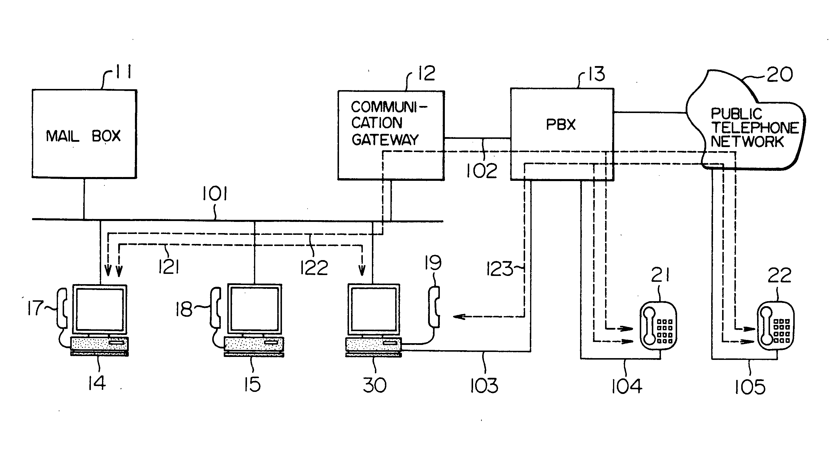
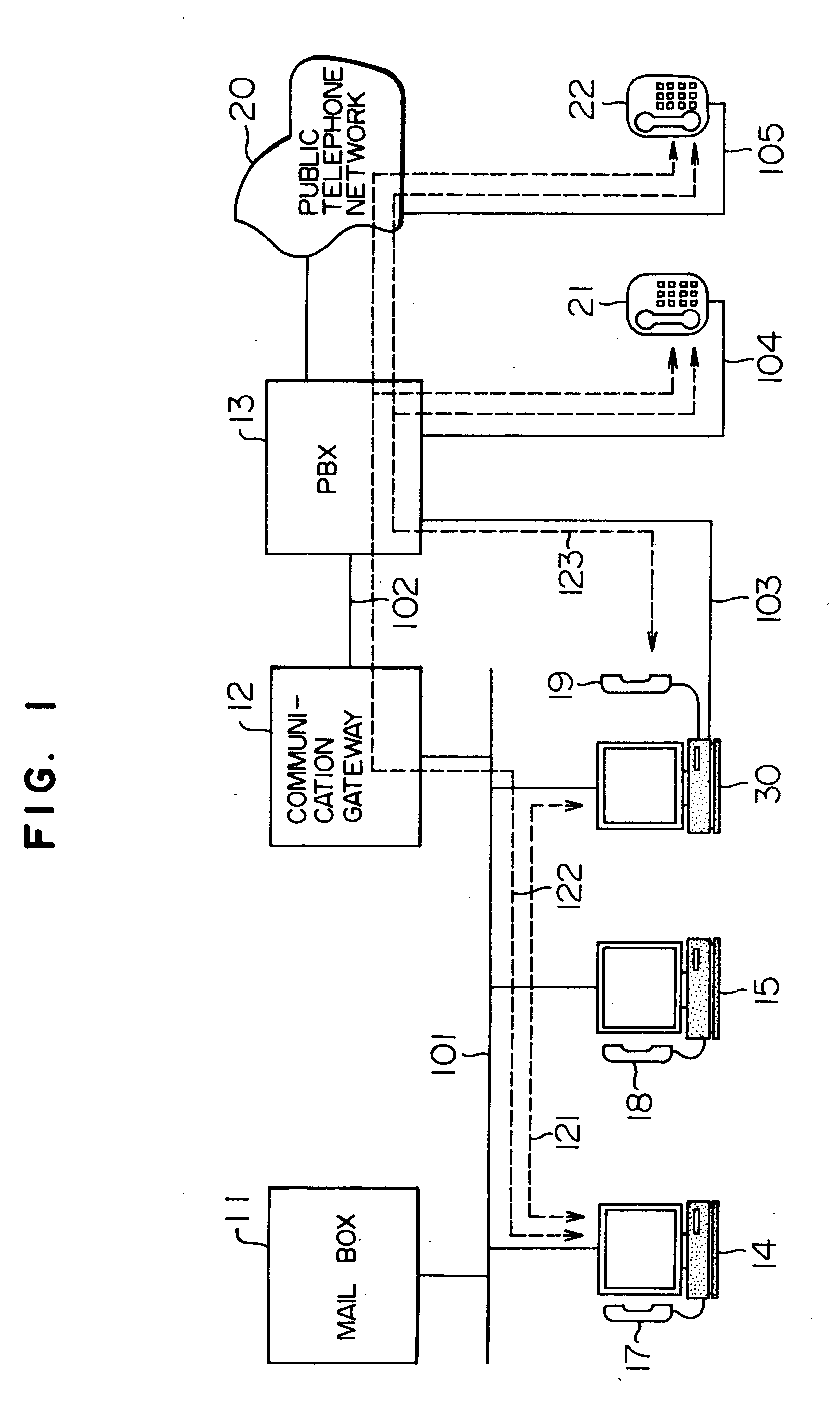
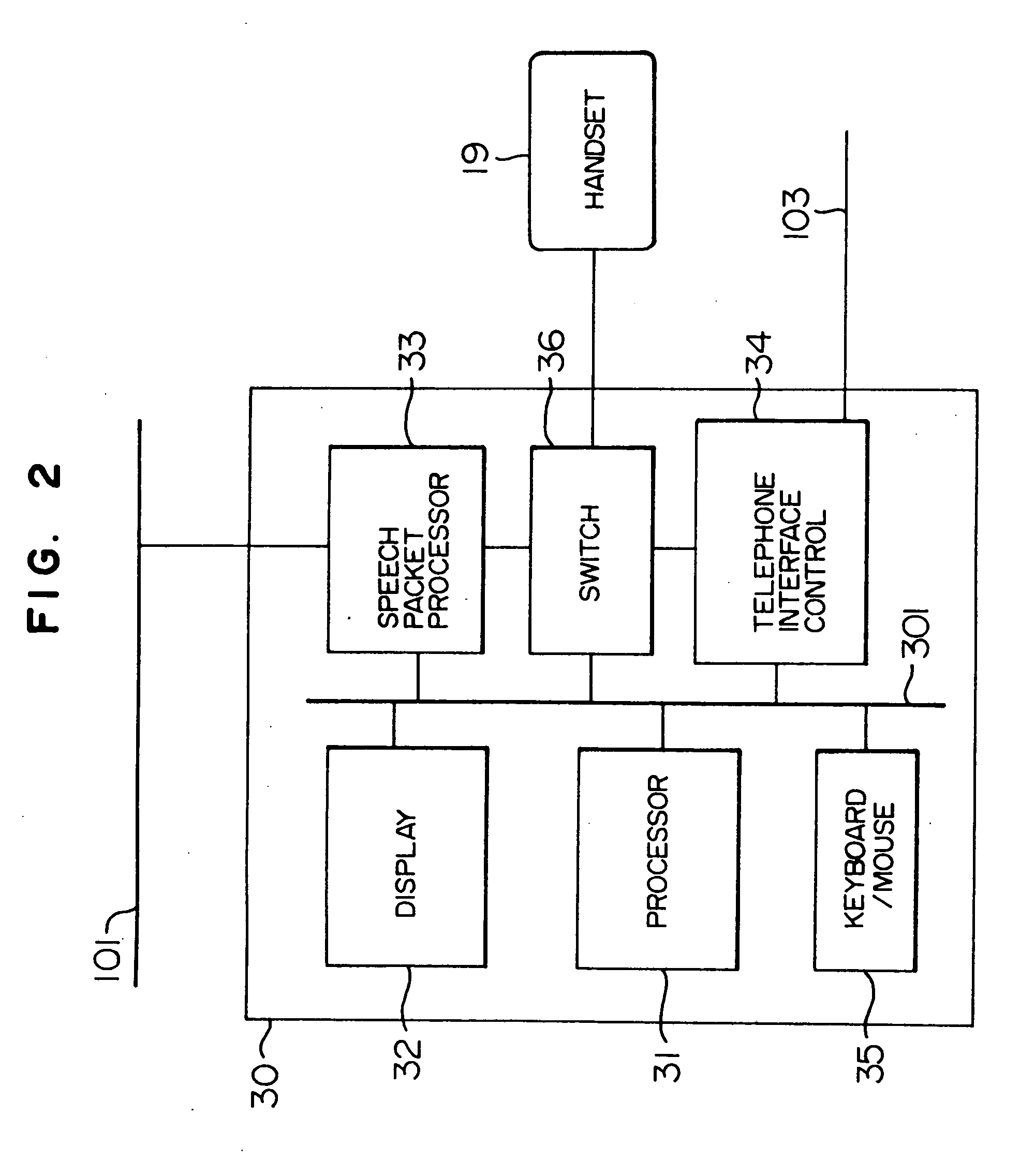
[0029]FIG. 1 shows the system structure of an embodiment of the packet communication system using the packet communication unit according to the present invention, and like reference numerals are used in FIG. 1 to designate like parts appearing in FIG. 4. Referring to FIG. 1, the reference numeral 30 designates a packet communication unit having a function of connection both of a conventional telephone network and a LAN 101 that is a packet communication network. The packet communication unit 30 is provided with a connection path for connection to the LAN 101 and a connection interface line 103 for connection to a private branch exchange network 13 that is the conventional telephone network. The connection interface line 103 provides the same interface as that for subscriber lines connected to telephones 21 and 22. The connection interface line 103 may be connected to ...


PUM


Abstract

The packet communication system enables communication between a communication unit connected in a conventional telephone network and a communication unit in a packet mode network. A device for exclusively selecting the connection network is provided so that, at the time of transmission of a signal from one communication unit to another, the connection path is selected according to the kind of the network to which the other communication unit belongs. At the time of signal reception, the communication unit is connected to only one of the conventional telephone network and the packet mode network. The packet communication system includes a packet processor for converting an information signal, such as speech, inputted from an input unit (for example, a transmitter microphone of a handset) into the form of a packet

Description

[0001] This is a continuation application of U.S. Ser. No. 10 / 396,824, filed Mar. 26, 2003; which is a continuation application of U.S. Ser. No. 09 / 238,160, filed Jan. 28, 1999 (now U.S. Pat. No. 6,563,815); which is a continuation application of U.S. Ser. No. 08 / 827,054, filed Mar. 26, 1997 (now abandoned); which is a continuation application of U.S. Ser. No. 08 / 486,183, filed May 9, 1995 (now U.S. Pat. No. 5,654,957).BACKGROUND OF THE INVENTION [0002] This invention relates to a packet communication system used for packet mode communication of a signal, such as, an audio signal or a video signal through a communication network, and more particularly to a packet communication system suitable for packet mode communication of a signal, such as, a speech signal between communication networks using signal types different from each other. [0003] With the recent progress of the architecture of a LAN (local area network), the network system connecting small size computers, such as, person...

Claims


Application Information

Patent Timeline
Patent Type & Authority Applications(United States)
IPC IPC(8): H04L12/66H04M3/00H04M1/253H04M3/42H04M3/428H04M3/533H04M7/00H04M7/12H04Q11/04
CPCH04L12/6418H04L2012/6481H04M1/2535H04M3/42323H04M7/12H04M3/533H04M7/0057H04M7/006H04M7/0069H04M3/428
Inventor KOYAMA, TOSHIAKI
Owner HITACHI LTD
Learn More