Anti-resonance noise device for tire

a technology of anti-resonance noise and tire, which is applied in the direction of non-skid devices, vehicle components, transportation and packaging, etc., can solve the problems of reducing the effectiveness of the device at reducing noise, reducing the closing of the groove, and reducing the noise inside the vehicle, so as to reduce the fault during demolding and the effect of mounding and demolding

Inactive Publication Date: 2015-08-27
MICHELIN & CO CIE GEN DES ESTAB MICHELIN +1
View PDF7 Cites 1 Cited by
  • Summary
  • Abstract
  • Description
  • Claims
  • Application Information

AI Technical Summary

Benefits of technology

[0022]The present invention, in an embodiment seeks to obtain a groove closure device that is easier to mound and demold by comparison with the known devices formed of blades secured to one of the walls delimiting a groove, the present invention very significantly reducing faults during demolding. Implementation of this device may concern any type of groove, whether this groove be oriented circumferentially, transversely or obliquely.

Problems solved by technology

This resonance of the air in the grooves has the result of generating, in a vehicle fitted with these tires, a noise inside the vehicle and a noise outside the vehicle.
However, it was found with this last type of membrane that incidents could occur during the demolding step: what happened was that bits of membrane could become torn, thereby correspondingly reducing the closing of the groove and the effectiveness of the device at reducing the noise.

Method used


Image

  • Anti-resonance noise device for tire
  • Anti-resonance noise device for tire
  • Anti-resonance noise device for tire

Examples


Embodiment Construction

[0048]In the figures accompanying this description, the same reference signs can be used to describe alternative forms of the invention as long as these reference signs refer to elements of a like nature, whether this nature be structural or indeed functional.

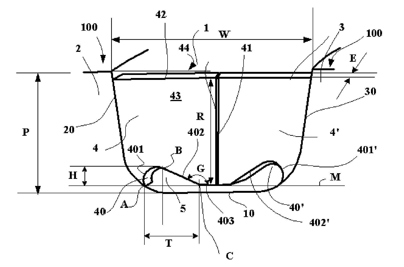
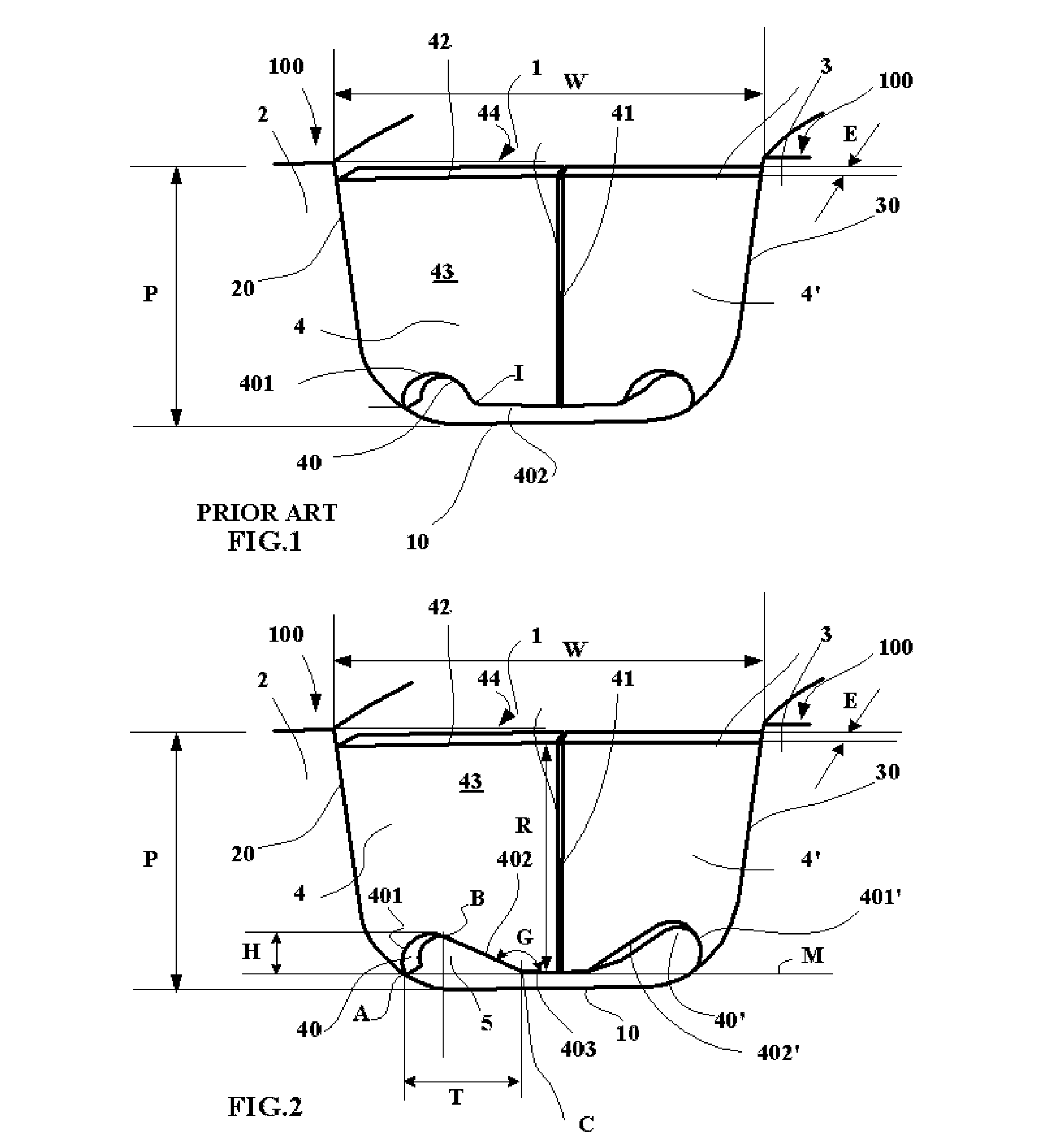
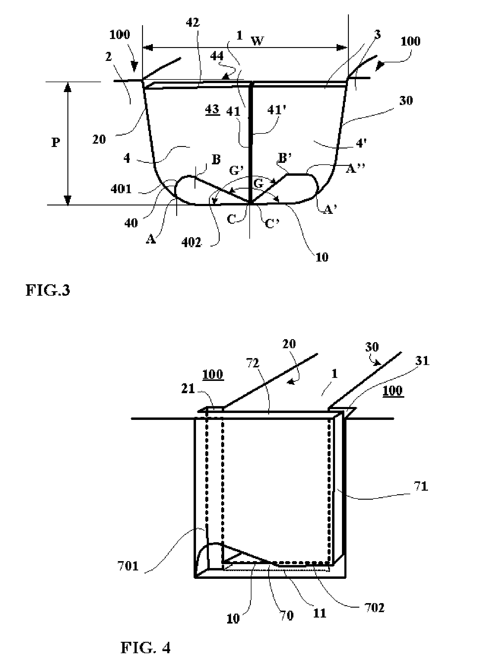
[0049]FIG. 1 shows, in cross section, a partial view of a tread according to the prior art, this tread being fitted to a tire of size 225 / 55 R 17. This figure depicts a groove 1 bounded by two raised elements 2, 3 of the tread, this groove 1 extending substantially in a circumferential direction of the tire on which the said tread is mounted. This groove 1, of width W—measured on the tread surface in the new state—equal to 13 mm and of depth P equal to 7.5 mm, is bounded by a first wall 20 and a second wall 30 that face one another and by a groove bottom 10 connecting these two walls together. The tread comprises a tread surface 100 intended to be in contact with a roadway during driving. In what follows, the bottom wall 10 of ...


PUM


Abstract

Tire tread, comprising at least one groove of width W and depth P which is delimited by two walls facing one another, these walls being joined together by a groove bottom, at least one groove comprising at least one flexible device for at least partially closing this groove as it enters the contact patch in which the tire is in contact with a roadway, each flexible device comprising at least one blade of a thickness suited to allowing it to flex under the effect of a circulation of liquid, this at least one blade being borne by a wall delimiting the groove, each blade of thickness E being bounded by a bottom wall facing the bottom of the groove, an end wall facing the other wall of the groove and a contact wall intended to come into contact with the roadway and lateral walls spaced apart from one another by a distance equal to the thickness E of the blade, this tread being such that the bottom wall of the blade comprises a first part extending between the points of connection with the wall bearing the blade, a second part extending the first part, this second part being extended by a third part as far as the end part of the blade, the first part and the second part being offset towards the outside with respect to a plane connecting the points of connection with the wall bearing the blade and the points of connection of the second part to the third part in order to form a notch of maximum height H in the bottom wall of the blade, this tread being characterized in that the angle between the second part and the third part is greater than 110 degrees and less than 180 degrees.

Description

[0001]This application is a 371 national phase entry of PCT / EP2013 / 069910, filed 25 Sep. 2013, which claims benefit of French Patent Application No. 1259031, filed 26 Sep. 2012, which is incorporated herein by reference for all purposes.BACKGROUND[0002]1. Field[0003]The present disclosure relates to tire treads and more particularly to treads comprising grooves comprising flexible devices for reducing the noise generated by air going into resonance inside these grooves during driving.[0004]2. Description of Related Art[0005]It is known that as a tire that is running comes into contact with a roadway in the contact patch, air is made to circulate in a pipe formed by a groove, notably by a groove of circumferential overall orientation and the roadway itself, this pipe being open at both of its ends.[0006]The air in this pipe forms a vibrating column of air the resonant frequency of which is dependent on the length between the two ends of the pipe and, therefore, on the length of groov...

Claims


Application Information

Patent Timeline
Patent Type & Authority Applications(United States)
IPC IPC(8): B60C11/13B60C19/00
CPCB60C11/1307B60C2011/1338B60C19/002B60C11/0309
Inventor BOURGEOIS, FREDERICBRUNEAU, FRANCOIS-XAVIERFICKINGER, PASCAL
Owner MICHELIN & CO CIE GEN DES ESTAB MICHELIN
Why Eureka
Try Eureka