Tomosynthesis imaging apparatus and method for operating the same

a technology of tomosynthesis and imaging apparatus, which is applied in the direction of x-ray tubes, patient positioning for diagnostics, applications, etc., can solve the problems of increasing the burden on the subject and relatively long imaging tim

Active Publication Date: 2020-04-02
FUJIFILM CORP
View PDF0 Cites 2 Cited by
  • Summary
  • Abstract
  • Description
  • Claims
  • Application Information

AI Technical Summary

Benefits of technology

[0021]According to the technology of the present disclosure, it is possible to provide a tomosynthesis imaging apparatus that can prevent the concentration of load on one radiation tube in a case in which a radiation source includes a plurality of radiation tubes and pre-imaging for setting the irradiation conditions of radiation in tomosynthesis imaging is performed and a method for operating the tomosynthesis imaging apparatus.

Problems solved by technology

Therefore, there is a problem that the imaging time is relatively long and a burden on the subject increases.
However, in a case in which the radiation source includes a plurality of radiation tubes, the following problems related to pre-imaging have been found.

Method used


Image

  • Tomosynthesis imaging apparatus and method for operating the same
  • Tomosynthesis imaging apparatus and method for operating the same
  • Tomosynthesis imaging apparatus and method for operating the same

Examples


first embodiment

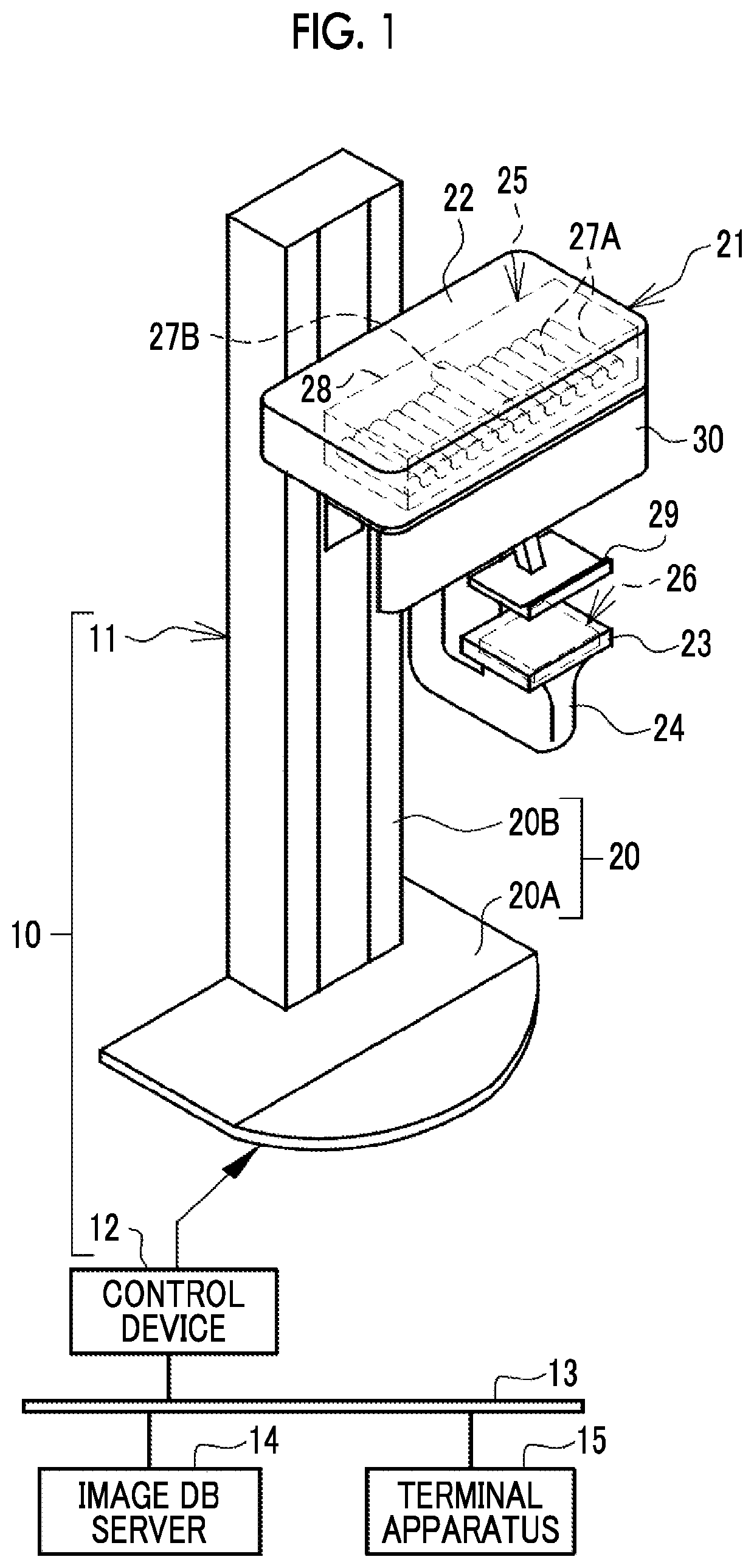
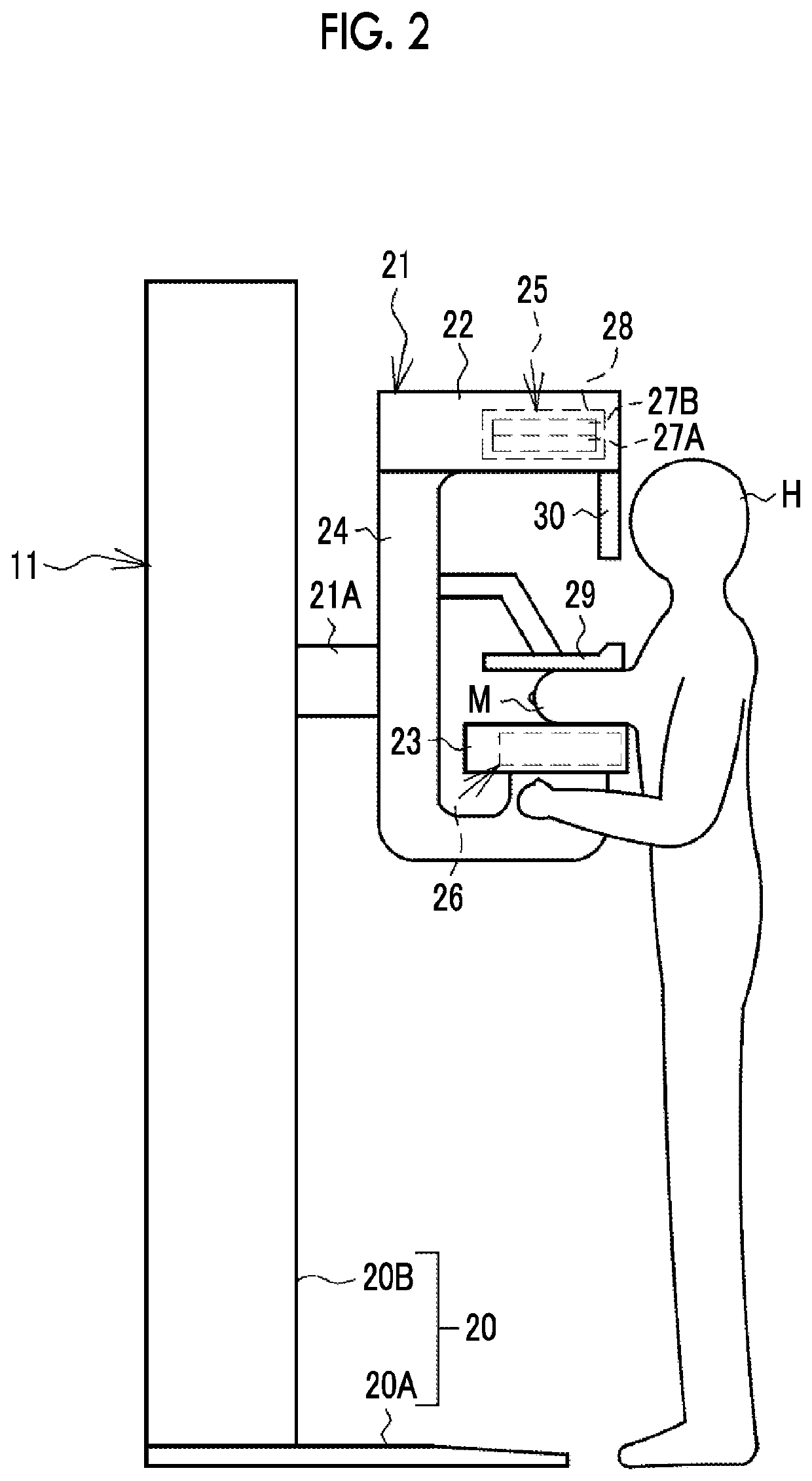
[0042]In FIGS. 1 and 2, a mammography apparatus 10 which is an example of a tomosynthesis imaging apparatus uses a breast M of a subject H as an object. The mammography apparatus 10 irradiates the breast M with radiation 37 (see, for example, FIG. 3), such as X-rays or y-rays, to capture a radiographic image of the breast M.

[0043]The mammography apparatus 10 includes an apparatus main body 11 and a control device 12. The apparatus main body 11 is installed, for example, in a radiography room of a medical facility. The control device 12 is installed, for example, in a control room next to the radiography room. The control device 12 is connected to an image database (hereinafter, referred to as DB) server 14 through a network 13, such as a local area network (LAN), such that it can communicate with the image DB server. The image DB server 14 is, for example, a picture archiving and communication system (PACS) server, receives a radiographic image from the mammography apparatus 10, and...

second embodiment

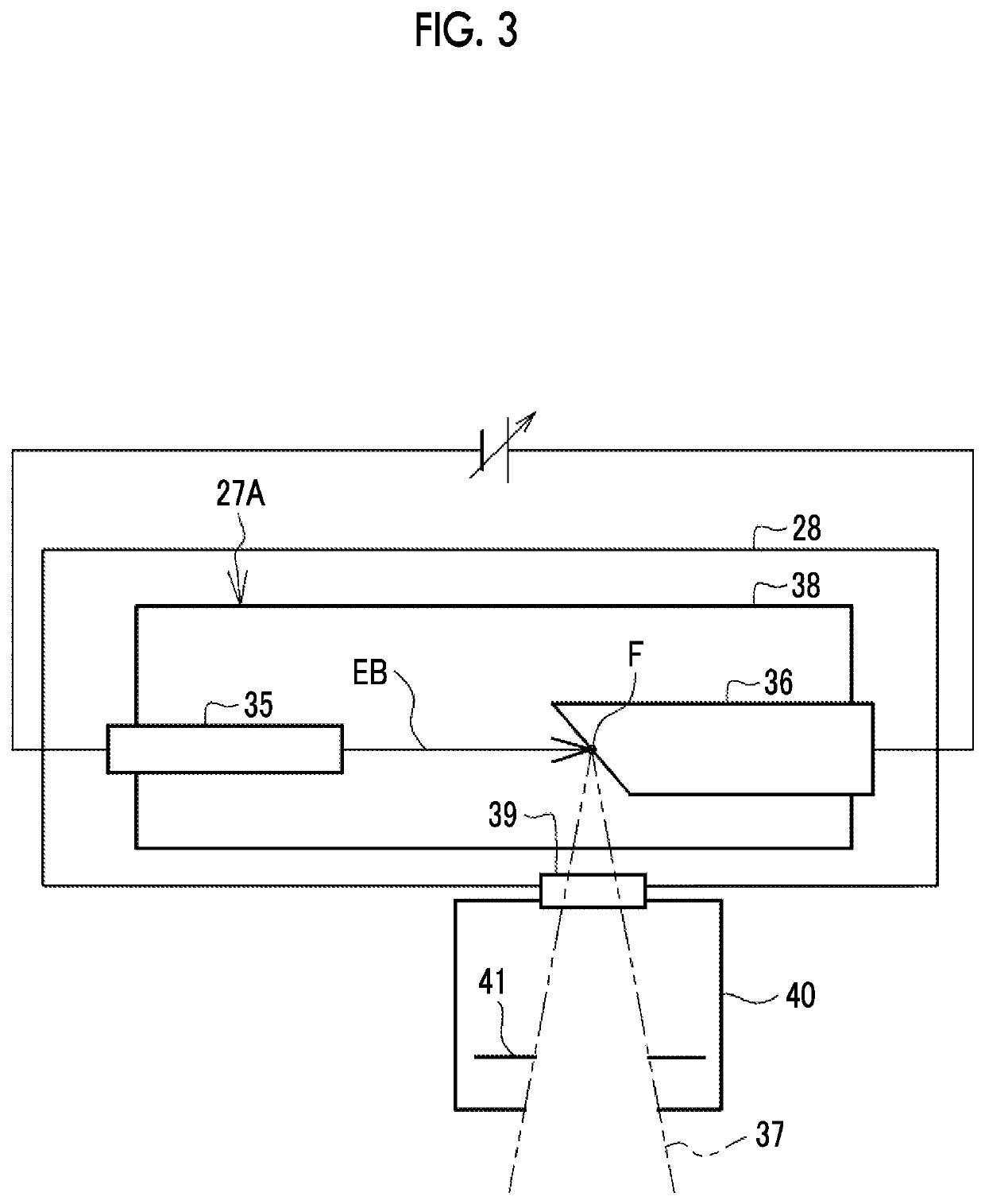
[0085]In a second embodiment illustrated in FIG. 12, a second radiation tube 27B_S having a smaller diameter than each of a plurality of first radiation tubes 27A is used.

[0086]In FIG. 12, the second radiation tube 27B_S is disposed at a position corresponding to the center of the maximum scanning angle between two adjacent first radiation tubes 27A. The second radiation tube 27B has a diameter φB less than the diameter φA of each of the plurality of first radiation tubes 27A (φB<φA). For example, φB is half of φA.

[0087]As such, in the second embodiment, the diameter φB of the second radiation tube 27B_S is less than the diameter φA of each of the plurality of first radiation tubes 27A. Therefore, the possibility that the regularity of the intervals D between the focuses F1 to F14 will be disturbed is reduced and the concern that the process related to the generation of the tomographic image T will be complicated is reduced, as compared to a case in which the first radiation tubes 2...

third embodiment

[0090]In a third embodiment illustrated in FIG. 14, a second radiation tube 27B_OR is disposed at a position outside the maximum scanning angle ψ.

[0091]In FIG. 14, the second radiation tube 27B_OR is disposed at a position outside the maximum scanning angle of tomosynthesis imaging which is defined by positions SP1 and S14 at both ends among a plurality of positions SP1 to SP14. In addition, the second radiation tube 27B_OR is disposed at a position that is outside the maximum scanning angle and is at a distance (an interval D in FIG. 14) equal to or less than the interval D between the focuses F1 to F14 from one (the position SP14 in FIG. 14) of the positions SP1 and SP14.

[0092]As such, in the third embodiment, the second radiation tube 27B_OR is disposed at a position outside the maximum scanning angle ψ. Therefore, there is no possibility that the regularity of the intervals D between the focuses F1 to F14 will be disturbed and no concern that the process related to the generatio...


PUM


Abstract

A radiation source of a mammography apparatus includes plural first radiation tubes and one second radiation tube. The first radiation tubes are used for tomosynthesis imaging. In contrast, the second radiation tube is used for pre-imaging which is performed before the tomosynthesis imaging in order to set the irradiation conditions of radiation in the tomosynthesis imaging. The first radiation tubes are provided at plural positions where the focuses of the radiation are set so as to be arranged in a linear shape or an arc shape at equal intervals. The second radiation tube is provided at a position that is offset from the plural positions where the first radiation tubes are provided to a rear side which is a side opposite to the irradiation side of the radiation.

Description

CROSS-REFERENCE TO RELATED APPLICATION[0001]This application claims priority from Japanese Patent Application No. 2018-182568, filed Sep. 27, 2018, the disclosure of which is incorporated herein by reference in its entirety.BACKGROUNDTechnical Field[0002]The technology according to the present disclosure relates to a tomosynthesis imaging apparatus and a method for operating the same.Related Art[0003]A tomosynthesis imaging apparatus has been known which performs tomosynthesis imaging that moves a radiation source to a plurality of positions with respect to a radiation detector and emits radiation from the radiation source at each position (for example, see JP2016-135319A). The focuses of the radiation at the plurality of positions to which the radiation source is moved are set so as to be arranged, for example, in an arc shape at equal intervals. In the tomosynthesis imaging, the radiation is emitted to an imaging surface of the radiation detector at a plurality of irradiation angl...

Claims


Application Information

Patent Timeline
Patent Type & Authority Applications(United States)
IPC IPC(8): A61B6/00A61B6/02H01J35/08H01J35/06
CPCA61B6/502A61B6/025A61B6/54H01J35/065A61B6/4007A61B6/488H01J35/112A61B6/04A61B6/4411A61B6/4441A61B6/0414A61B6/107A61B6/5205A61B6/027A61B6/4452
Inventor SATO, MASARUMATSUURA, MASAYOSHI
Owner FUJIFILM CORP
Why Eureka
Try Eureka