Electronic camera and battery voltage controlling method employed therein for successively, rather than simultaneously, operating camera portions during conditions of low battery voltage

a technology which is applied in the field of electronic cameras and battery voltage controlling methods employed there, can solve the problems of large load, inability to achieve proper signal processing, and inability to meet the requirements of the camera portion,

Inactive Publication Date: 2006-05-23
SANYO ELECTRIC CO LTD
View PDF29 Cites 2 Cited by
  • Summary
  • Abstract
  • Description
  • Claims
  • Application Information

AI Technical Summary

Benefits of technology

[0008]One object of the present invention is to provide an electronic camera and a battery voltage controlling method employed therein which are free from failures of an internal circuit, such as a signal processing portion, when a small amount of electric charge remains in a battery.
[0009]Another object of the present invention is to provide an electronic camera and a battery voltage controlling method employed therein, wherein when a small amount of electric charge remains in a battery, dropping of battery voltage is reduced and failures of an internal circuit, such as a signal processing portion, is thus prevented.
[0010]Still another object of the present invention is to provide an electronic camera and a battery voltage controlling method employed therein, wherein when a small amount of electric charge remains in a battery, the concentration of load on the battery is avoided to reduce the dropping of battery voltage and thereby prevent failures of an internal circuit, such as a signal processing portion.

Problems solved by technology

With an electronic camera equipped with an electronic flash device, an LCD monitor and the like, however, the load of the electronic flash device, LCD monitor and the like which receive power supplied from the battery as well as the inherent load of the camera portion, such as a CCD imager and a signal processing circuit, poses a significant problem.
Thus, when the capacitor for the electronic flash is charged during either light emission or non-light emission in preparation for the next light emission, a large current will flow from the battery and cause a large load.
Thus, when battery voltage has significantly dropped, it falls below the lower limit at which the integrated circuits and microcomputers can properly operate, and proper signal processing might not be achieved.

Method used


Image

  • Electronic camera and battery voltage controlling method employed therein for successively, rather than simultaneously, operating camera portions during conditions of low battery voltage
  • Electronic camera and battery voltage controlling method employed therein for successively, rather than simultaneously, operating camera portions during conditions of low battery voltage
  • Electronic camera and battery voltage controlling method employed therein for successively, rather than simultaneously, operating camera portions during conditions of low battery voltage

Examples


Embodiment Construction

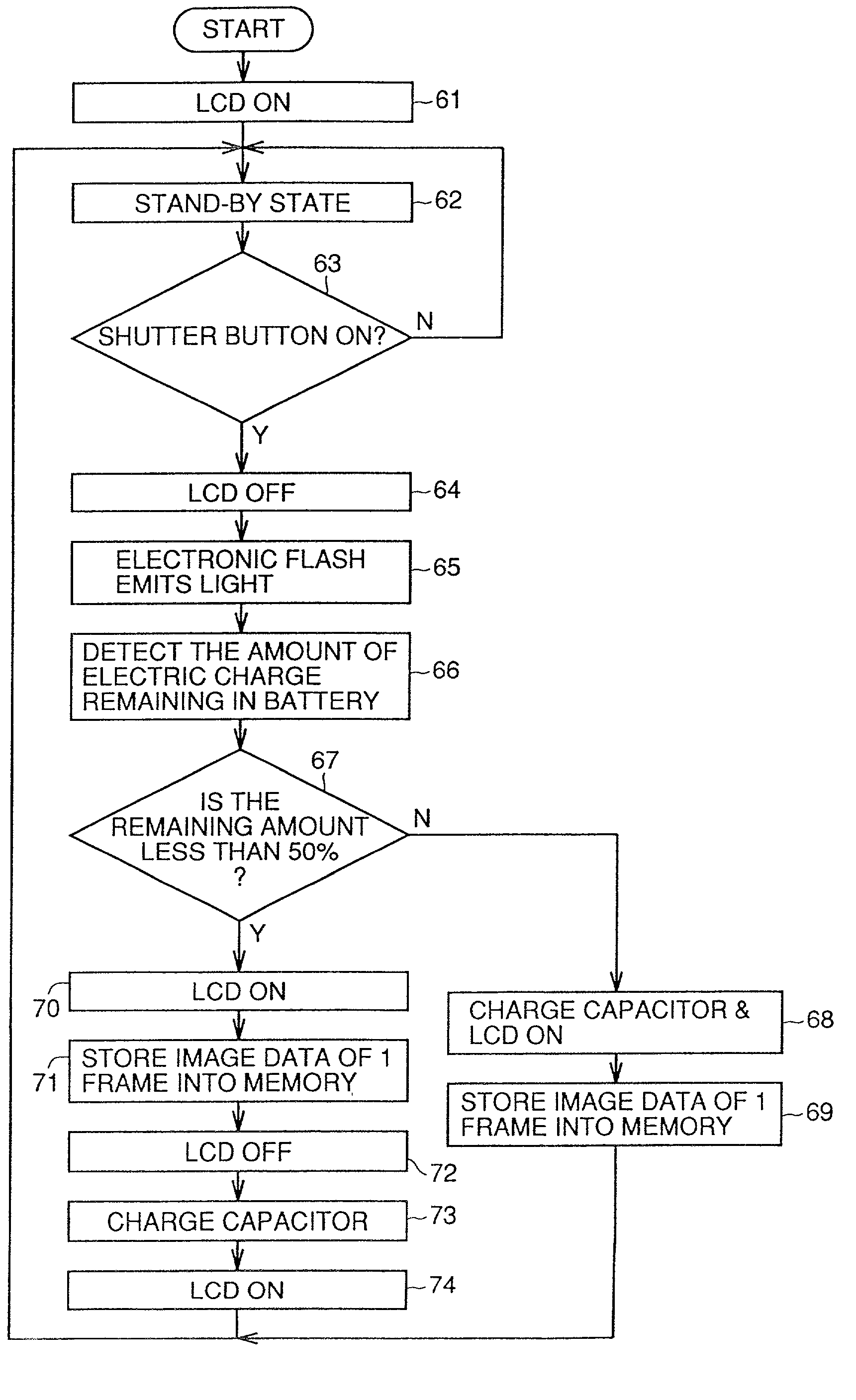
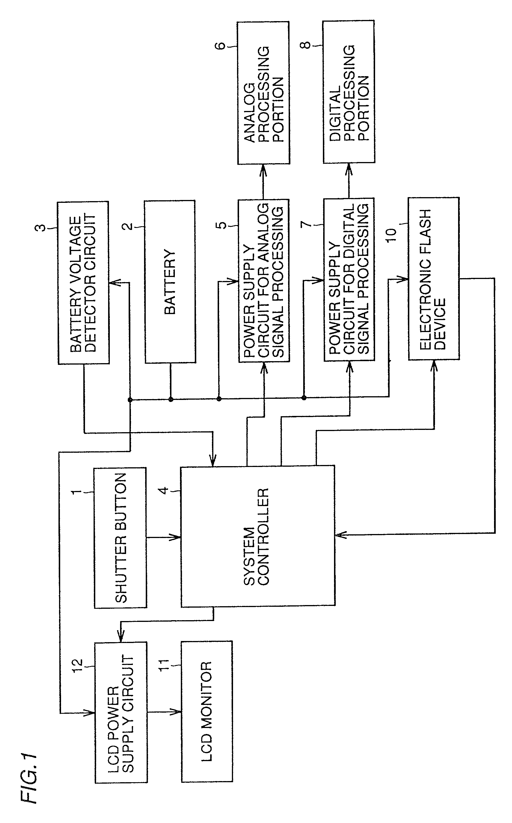
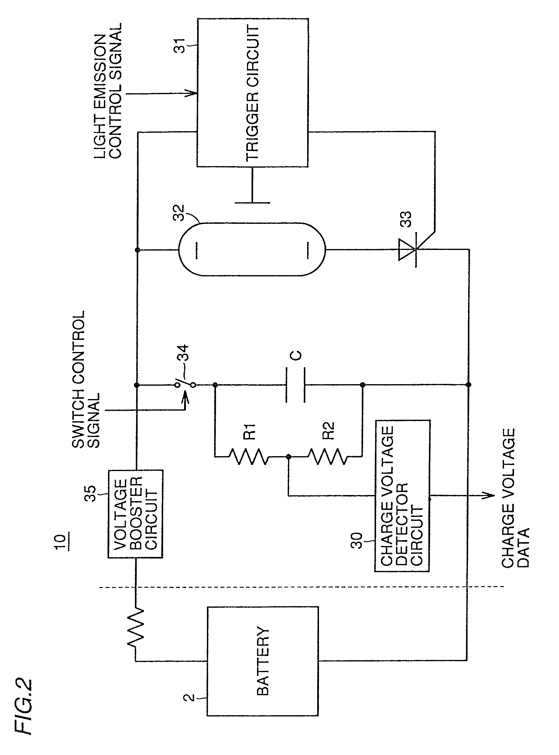
[0027]Referring to FIG. 1, a digital still camera as one embodiment of the present invention includes: a shutter button 1 via which the user provides an instruction to the camera; a battery 2 removably mounted on the camera; a battery voltage detector circuit 3 for detecting the voltage value at the output stage of battery 2, applying analog-digital conversion of the detected voltage value and outputting the converted voltage value; a system controller 4 receiving an instruction from shutter button 1 and an output from battery voltage detector circuit 3 for controlling the driving of the power supply circuit 5 for processing analog signals, power supply circuit 7 for processing digital signals and LCD power supply circuit 12 described later and for generating various control signals to an electronic flash device 10; an analog processing portion 6 configured of a drive circuit for a CCD imager or the like for processing a video signal in the analog stage; a digital processing portion...


PUM


Abstract

An electronic camera free from failures of an internal circuit, such as a signal processing portion, caused by a drop in battery voltage when there remains a small amount of electric charge in the battery, includes a signal processing portion for signal-processing an imaged video signal obtained from an imaging element to form image data, a monitor for displaying the image data, an electronic flash device, a battery for supplying current to the signal processing portion, the monitor and the electronic flash device, a battery voltage detector circuit, and a system controller. The electronic flash device includes a capacitor charged when no light is emitted, and a discharged tube receiving an output from the capacitor and emitting light. The system controller receives an output from the battery voltage detector circuit, determines whether the amount of electric charge remaining in the battery is below a predetermined value, and controls displaying on the monitor and charging of the capacitor not to be simultaneously performed when the amount of electric charge remaining in the battery is below the predetermined value.

Description

BACKGROUND OF THE INVENTION[0001]1. Field of the Invention[0002]The present invention relates to an electronic camera which is provided with an electronic flash and an LCD monitor and uses a battery as a power supply, and to a battery voltage controlling method employed therein.[0003]2. Description of the Background Art[0004]In recent years, electronic cameras in which an image formed by a CCD imager is signal-processed and stored in a recording medium, such as a flash memory, are in common use. In particular, the type integrally equipped with various accessories, such as an electronic flash device and an LCD monitor, commercially preferred.[0005]Typically, this electronic camera uses a battery, such as a dry cell and a secondary cell, as a power supply. Thus, desirably, the load on the battery is reduced as much as possible to contemplate longer life time of the battery itself and variations of battery voltage are also suppressed. With an electronic camera equipped with an electron...

Claims


Application Information

Patent Timeline
Patent Type & Authority Patents(United States)
IPC IPC(8): H04N5/222H04N5/225G01R31/36H02J1/00H02J7/00H04N5/232H04N5/235H04N101/00
CPCH04N5/2354H04N5/232H04N23/651H04N23/633H04N23/74H04N23/65
Inventor AKIZUKI, HIROSHIDOTSUBO, NOBUHIDE
Owner SANYO ELECTRIC CO LTD
Why Eureka
Try Eureka