
Grip heater control apparatus

a control apparatus and heater technology, applied in the direction of mechanical control devices, steering devices, instruments, etc., can solve the problems of starter motor, battery voltage drop below a minimum voltage, excessive amount of electricity to the heater, etc., to prevent an unstable operation and prevent excessive battery voltage drop away

Active Publication Date: 2007-11-06
FALTEC CO LTD +1
View PDF6 Cites 8 Cited by
  • Summary
  • Abstract
  • Description
  • Claims
  • Application Information

AI Technical Summary

Benefits of technology

The present invention provides a grip heater control apparatus for vehicles that increases opportunities to warm the grip while reducing battery voltage drop. The apparatus includes a heater for generating heat, a generator for generating electricity interlocking with the engine, and a battery charged by the generator. The apparatus includes a revolutions detecting unit for detecting the number of revolutions of the engine or the generator, and a heater control unit for controlling the electric energy supplied to the heater based on the detected number of revolutions. This allows for a more efficient use of the heater's electricity and reduces the battery voltage drop. The apparatus can also control the electric energy to be lower than a maximum level when the detected number of revolutions is equal to or lower than a predetermined number of revolutions. This further increases the opportunities to warm the grip while reducing the battery voltage drop.

Problems solved by technology

In the grip heater control apparatus disclosed in the patent document 1, however, if the driver operates the dial for temperature adjustment to increase the temperature of the heater at a low engine speed, the amount of electricity to the heater becomes excessive relative to the amount of power generation of the generator, which could lead to a situation where the battery voltage drops below a minimum voltage required to drive the starter motor.
This increases the occasions where the driver cannot warm the grip when he desires.
Particularly when the battery supplies power to a lamp or other electric equipment other than the heater or when the battery voltage cannot go up enough due to the battery deterioration, the grip heater control apparatus has a disadvantage of increasing the cases where the driver substantially cannot operate the heater.

Method used


Image

  • Grip heater control apparatus
  • Grip heater control apparatus
  • Grip heater control apparatus

Examples


Embodiment Construction

[0037]The preferred embodiment of the present invention will now be described in detail hereinafter with reference to the accompanying drawings. In this embodiment, an autobicycle (motorcycle) is taken for example as a vehicle provided with a grip heater control apparatus, which is the embodiment of the present invention.

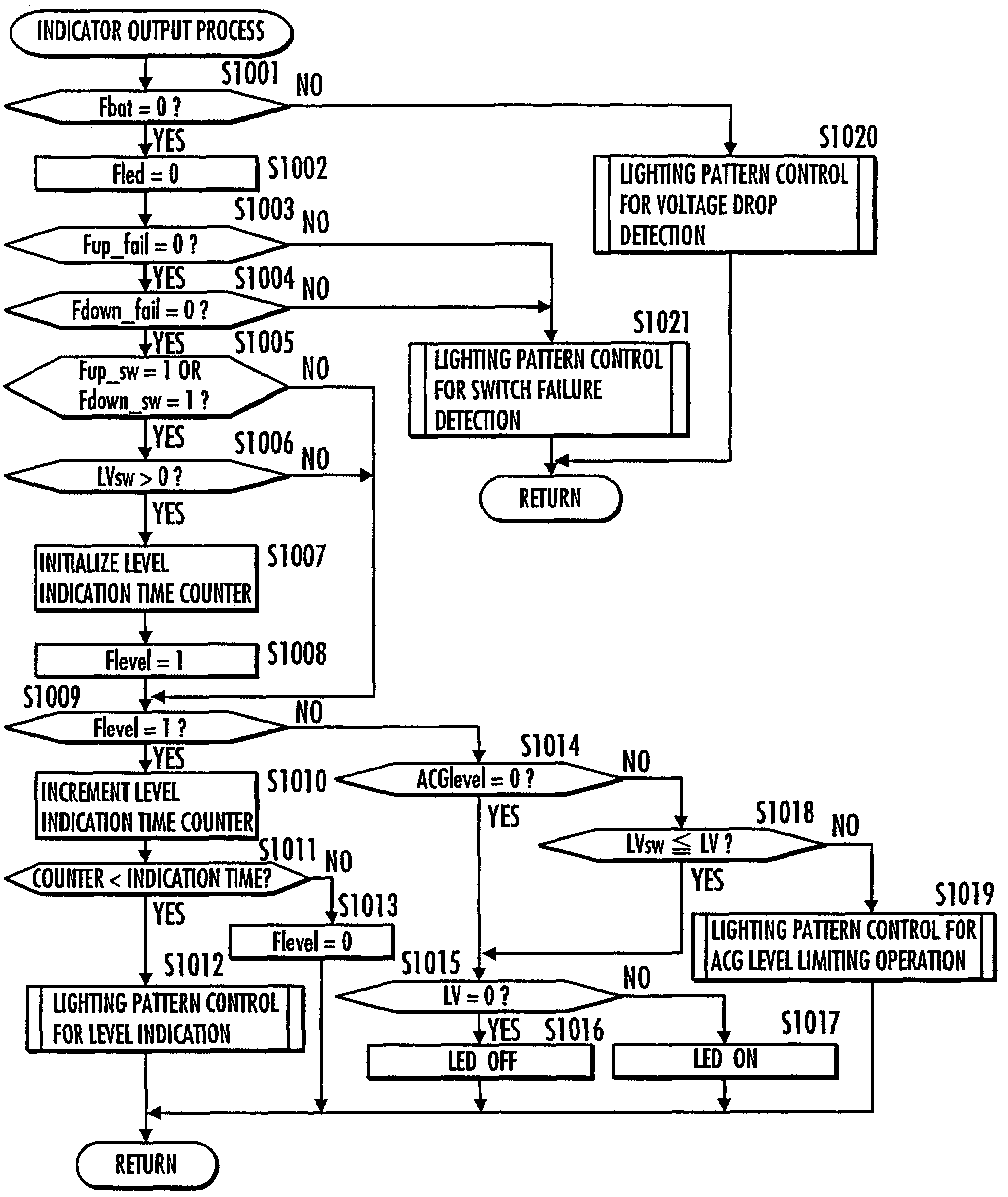
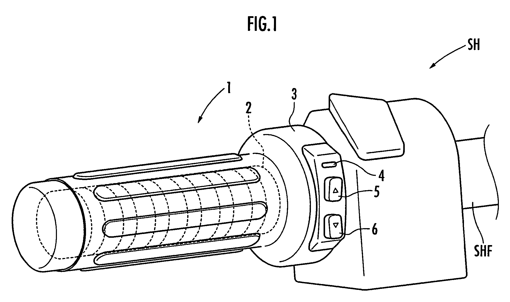
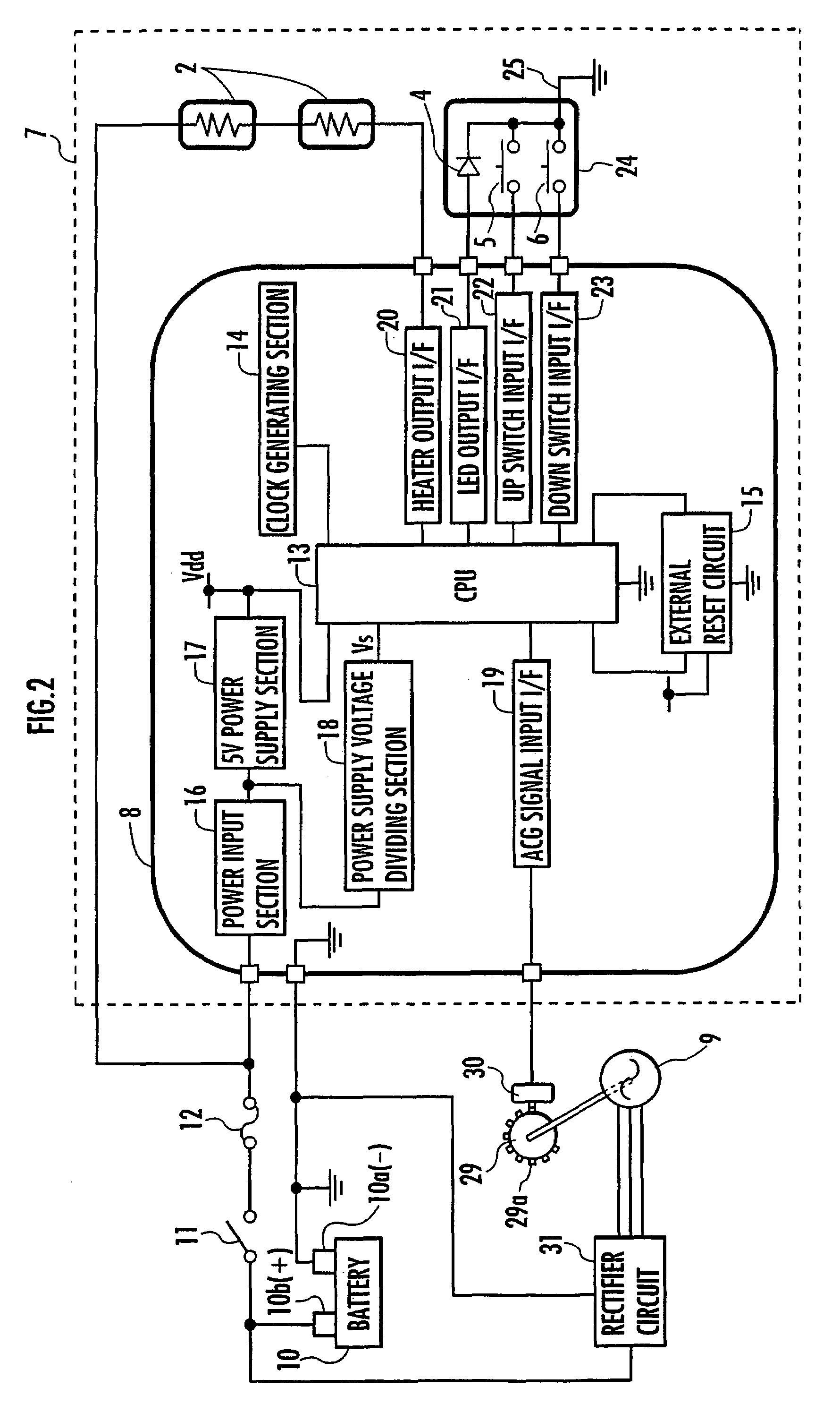
[0038]First, referring to FIG. 1, there is shown the grip heater control apparatus according to the embodiment for controlling the electric energy to a heater (electric heater) 2 made of a flexible printed-wiring board or the like incorporated in each of a left grip 1 and a right grip not shown, each of which is provided in a steering handle SH of the motorcycle. The left grip 1 and the right grip are made of rubber or other resin each in the form of a cylinder with a bottom and inserted around each end (the left end and the right end) of a frame SHF of the steering handle SH, respectively. The heater 2 for the left grip 1 is placed between the internal perimeter su...


PUM


Abstract

A grip heater control apparatus (7) capable of increasing the opportunities to enable a heater (2) to warm a grip (1) while suppressing a voltage drop of a battery (10), the grip heater control apparatus comprising a heater (2) for generating heat by means of electric power supplied from the battery (10), the heater being provided in a grip (1) of a steering handle of a vehicle having a generator (9) for generating electricity interlocking with the rotation of an engine as a propulsive source and the battery (10) charged by the generator (9), and a heater control unit for controlling the electric energy supplied to the heater (2) from the battery (10), wherein a revolutions detecting unit is provided for detecting the number of revolutions of the engine or the generator (9) and the heater control unit includes a unit for determining an upper limit on the upper limit electric energy supplied to the heater (2) depending on the detected number of revolutions.

Description

BACKGROUND OF THE INVENTION[0001]1. Field of the Invention[0002]The present invention relates to a control apparatus for a heater provided in a grip of a steering handle of a vehicle such as a motorcycle, a snowmobile, or a wet bike.[0003]2. Related Background Art[0004]Conventionally, there is an already known technology of providing a comfortable driving environment for a driver by providing a heater (an electric heater) in a grip (a part gripped by the driver) of a steering handle and controlling the amount of electricity supplied to the heater to warm the grip in a vehicle having an engine as a propulsive source such as a motorcycle, a snowmobile, and a wet bike (for example, refer to Japanese Laid-Open Patent Publication No. 2004-75047 (hereinafter, referred to as patent document 1)). The apparatus in the patent document 1 has a variable resistor in a circuit for controlling the amount of electricity supplied to the heater and adjusts the amount of electricity supplied to the he...

Claims


Application Information

Patent Timeline
Patent Type & Authority Patents(United States)
IPC IPC(8): H05B1/02
CPCB62J33/00B62K21/26Y10T74/20828Y10T74/20864
Inventor OISHI, YASUOOKAMOTO, KATSUYA
Owner FALTEC CO LTD
Learn More