Transformer

A technology for transformers and flanges, which is applied in the field of transformers and can solve problems such as difficulty and size reduction

Inactive Publication Date: 2007-05-16
HANWA ALPHA BUSINESS
View PDF1 Cites 7 Cited by
  • Summary
  • Abstract
  • Description
  • Claims
  • Application Information

AI Technical Summary

Problems solved by technology

However, in the above-mentioned transformer, although it is possible to reduce the size of the height, it is difficult to reduce the size in the front-rear direction.

Method used


Image

  • Transformer
  • Transformer
  • Transformer

Examples


no. 2 approach

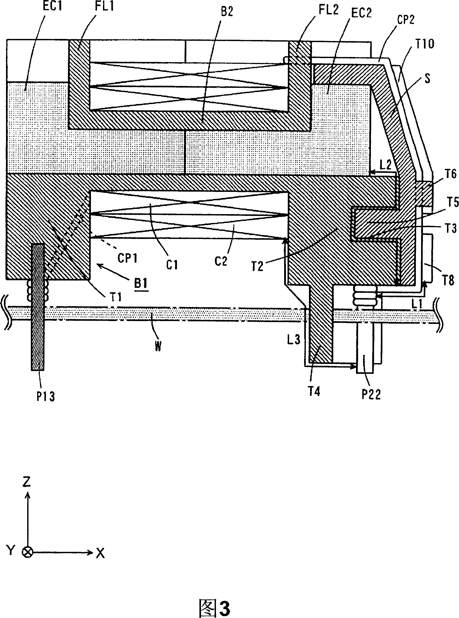
[0068] Fig. 5 is a sectional view related to the second embodiment.

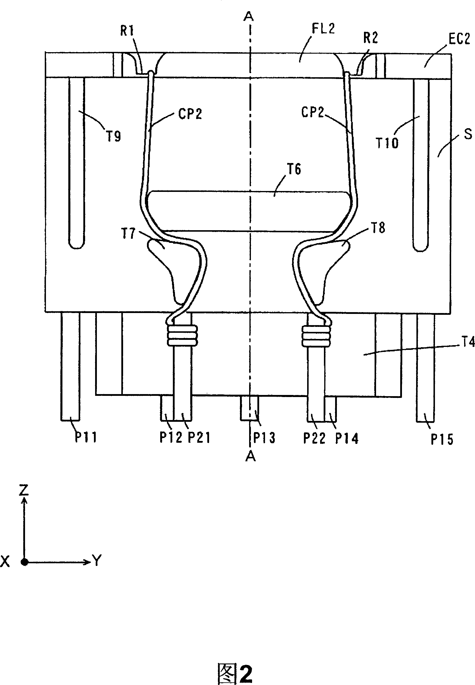
[0069] In FIG. 5 , directions perpendicular to each other are indicated by X, Y, and Z axes. The direction of the arrow X is the front side, the direction opposite to the arrow X is the back side, the direction of the arrow Y is the side side, the direction of the arrow Z is the upper side, and the direction opposite to the arrow Z is the lower side side.

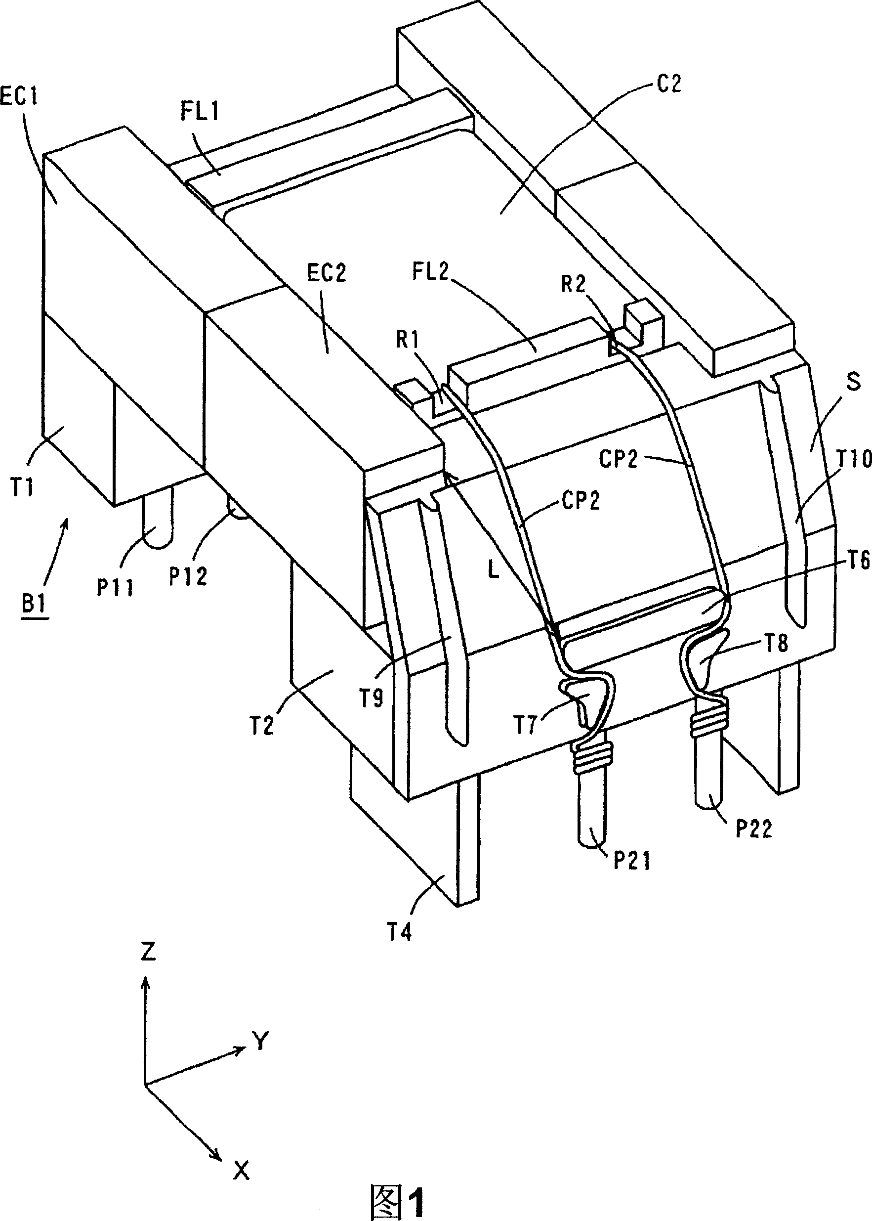
[0070] The transformer shown in FIG. 5 includes a bobbin B11, a primary coil C1, a secondary coil C2, E-shaped cores E1, E2, pin terminals P31, P32, and an insulating member S1.

[0071] Coil B11 is composed of winding part B12 around which primary coil C1 and secondary coil C2 are wound, flange part FL11 formed at the lower end of winding part B12, and flange part FL12 formed at the upper part of winding part B2. Wherein, the bobbin B11 is integrally formed of an insulating material such as plastic.

[0072] On the back side of the flange portion FL11...


PUM


Abstract

The invention provides a transformer which includes a bobbin, a primary coil, a secondary coil, an E-type core, a plurality of pin terminals, and an insulation member. The bobbin has a winding portion where the primary coil and the secondary coil are wound, a flange portion formed at the end of the rear side of the winding portion, and a flange portion formed at the end of the front of the winding portion. An insulating protrusion having an insulating concave is arranged at the lower side of the flange portion formed at the end of the front of the winding portion. The insulation member is mounted on a heat-radiation protrusion and the E-type core so that an insulating convex is engaged with the insulating concave. The pull-out line of the secondary coil is guided above the surface of the insulation member and connected to the pin terminal.

Description

technical field [0001] The present invention relates to transformers that electrically insulate a primary coil from a secondary coil. Background technique [0002] In order to secure the insulation distance between the primary coil and the secondary coil, there has been proposed a transformer in which an insulating protruding portion is provided on one flange portion of the bobbin. (refer to patent document 1) [0003] Fig. 6 is a cross-sectional view showing an example of the prior art. Among them, in FIG. 6, directions perpendicular to each other are indicated by X, Y, and Z axes. The direction of the arrow X is the front side, the direction opposite to the arrow X is the back side, the direction of the arrow Y is the side side, the direction of the arrow Z is the upper side, and the direction opposite to the arrow Z is the lower side side. [0004] As shown in FIG. 6 , the bobbin 10 has flange portions 102 and 103 at both ends of the winding portion 101 . The primary...

Claims


Application Information

Patent Timeline
IPC IPC(8): H01F27/32H01F27/28H01F30/00H01F27/22
CPCH01F27/22H01F2027/297H01F27/325
Inventor 角田兼教
Owner HANWA ALPHA BUSINESS
Why Eureka
Try Eureka