
Insulator, motor and compressor

A technology for insulators and wires, applied in the field of motors, compressors, and insulators, can solve problems such as wire damage, achieve the effects of inhibiting damage, reducing bending angles, and increasing contact area

Inactive Publication Date: 2010-10-06
DAIKIN IND LTD
View PDF11 Cites 2 Cited by
  • Summary
  • Abstract
  • Description
  • Claims
  • Application Information

AI Technical Summary

Problems solved by technology

[0017] Then, there is a problem of damage to the electric wire due to vibration

Method used


Image

  • Insulator, motor and compressor
  • Insulator, motor and compressor
  • Insulator, motor and compressor

Examples


Embodiment Construction

[0098] Hereinafter, embodiments of the compressor of the present invention will be described with reference to the drawings.

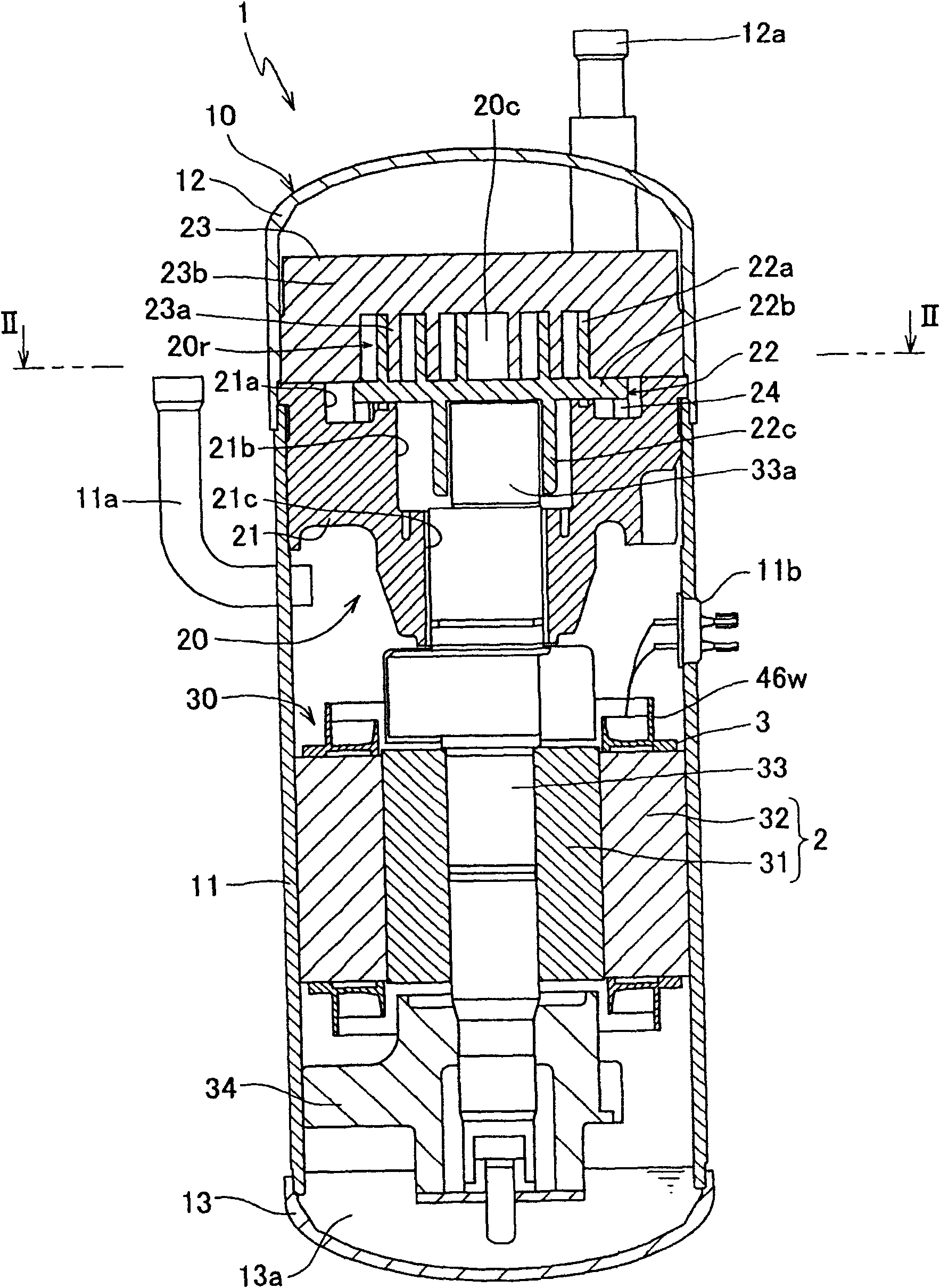
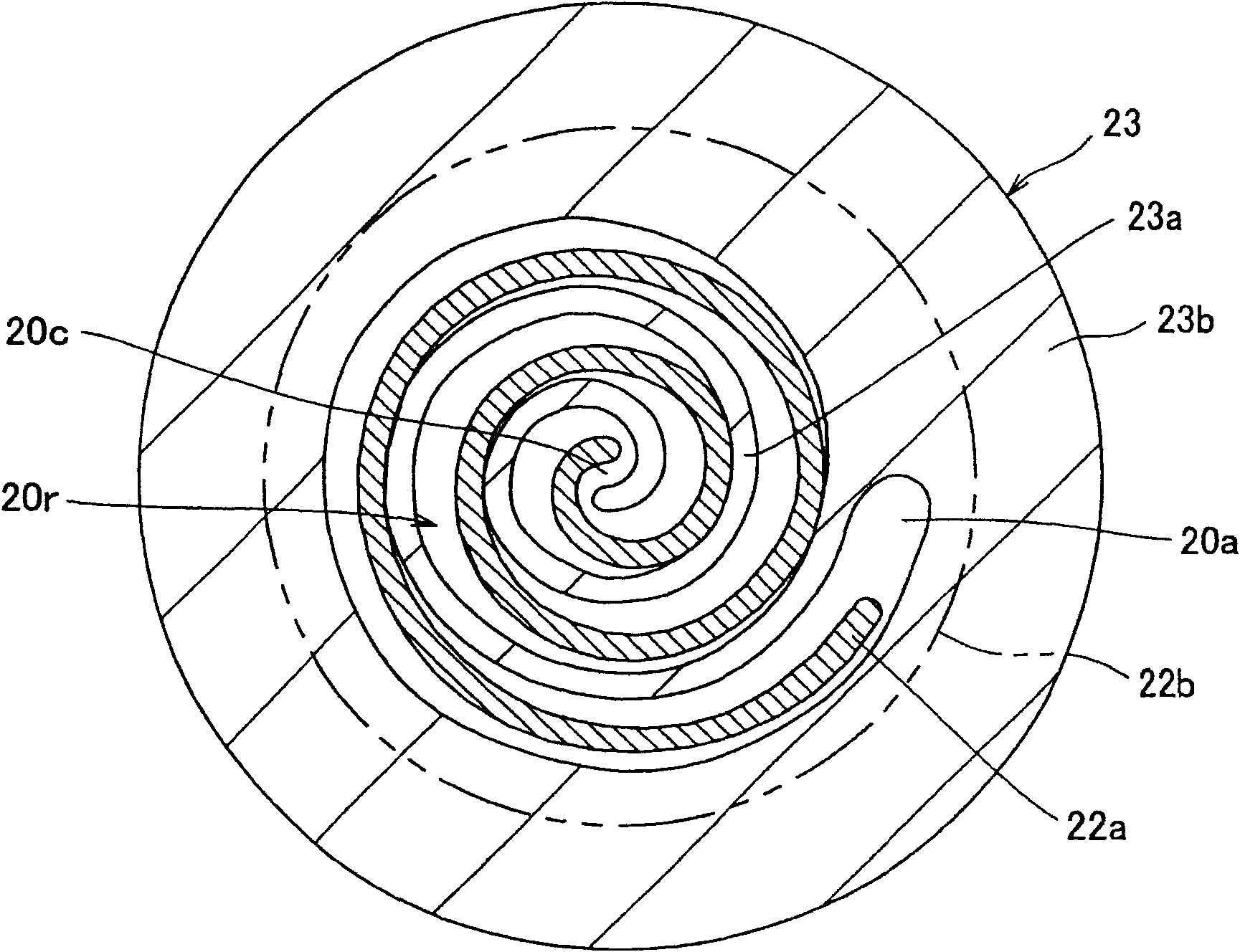
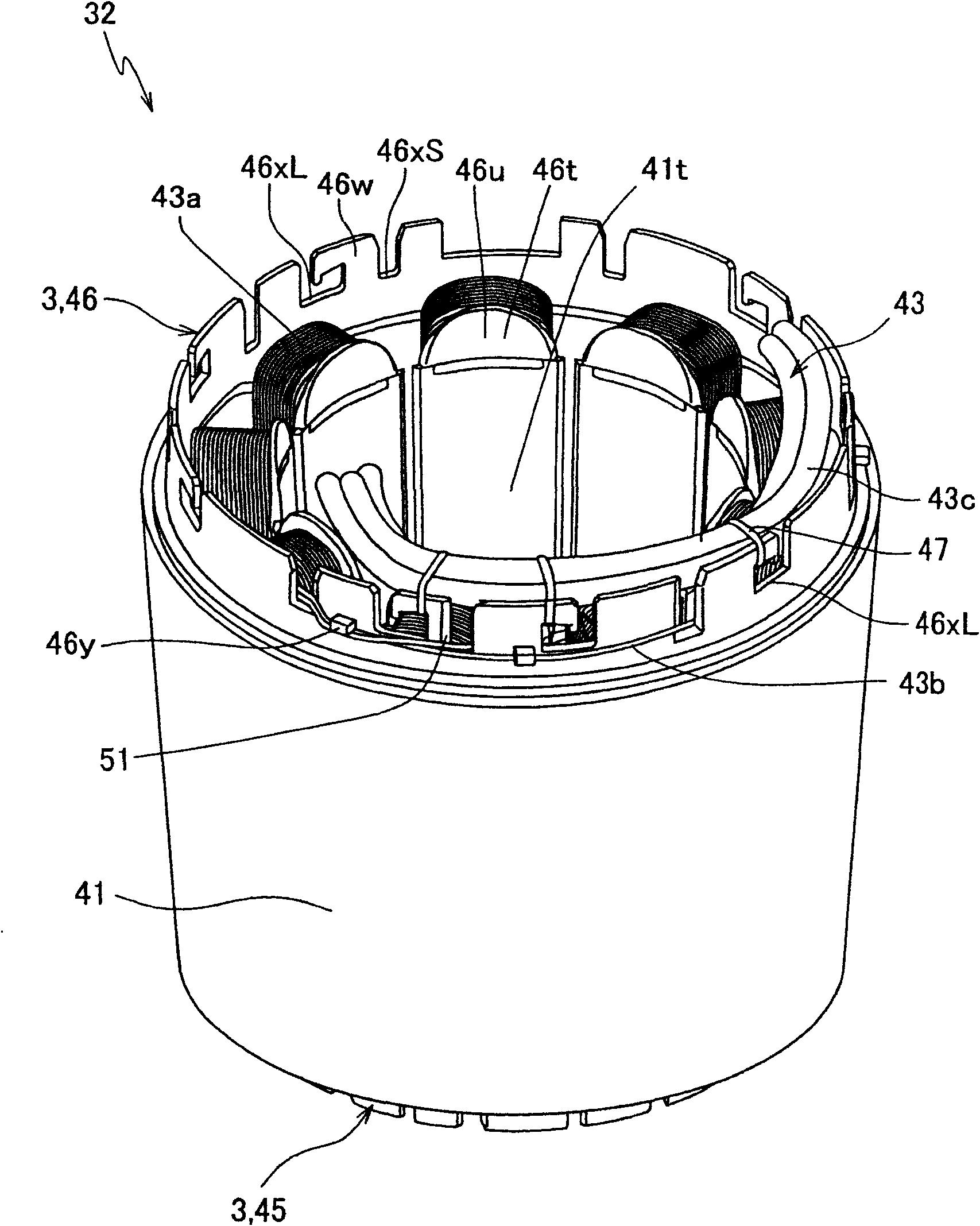
[0099] figure 1 It is a sectional view showing the overall structure of the compressor. figure 2 for figure 1 The compressor shown has a compression mechanism 20 figure 1 The II-II line sectional view in. image 3 to represent figure 1 The compressor shown has a perspective view of the stator of the electric motor. Figure 4 for the front view image 3 A diagram of the core of the stator is shown. Figure 5 for image 3 A perspective view of the insulator of the stator is shown. Image 6 for the front view Figure 5 A diagram of the insulator is shown. Figure 7 for the front view image 3 A diagram showing the periphery of a groove in the peripheral wall portion of the insulator. Figure 8 to represent only Figure 7 A diagram of the peripheral wall portion shown. Figure 9 with Figure 10 to represent image 3 A partially enlarged pe...


PUM


Abstract

The invention provides an insulator, a motor and a compressor, which inhibits stress applied to a wire when equipping wires inside and outside an insulator wall surface of the motor stator and prevents damage owing to press and vibration to an angle portion. The insulator has a circular periphery wall portion (46w) which extends along the shaft direction of a core portion and forms a groove (46xS) allowing the wire (43b) to pass. An inclination surface (51) which is inclined in the racial direction of the core portion relative to the axial direction of the core portion is formed in one wall portion (46wL) in wall portions on two sides of the groove (46xS) in the periphery wall portion (46w) and on the periphery side of the end portion opposite to another wall portion (46wR). The wire (43b) is disposed along the inclined surface (51).

Description

technical field [0001] The present invention relates to insulators for electric motor stators, electric motors and compressors. Background technique [0002] Conventionally, various compressors have been developed that compress refrigerant using the rotation of an electric motor. For example, there is a scroll compressor that compresses refrigerant in compression chambers formed between a fixed scroll and a movable scroll each having a spiral lap. In this compressor, an electric motor is used to rotate the movable scroll eccentrically. [0003] In such a motor, for example, a power supply and each winding section are connected to supply current from the power supply to the winding section (coil). In addition, for example, in order to provide a neutral point, each winding part is connected separately. [0004] Patent Documents 1 to 3 disclose insulators provided with terminals for such connection. [0005] In addition, Patent Document 4 discloses an insulator that enables...

Claims


Application Information

Patent Timeline
Patent Type & Authority Applications(China)
IPC IPC(8): H02K3/34H02K3/38
Inventor 平野雅敏塚本聪
Owner DAIKIN IND LTD
Learn More