Real-time transmission buoy device

A technology of real-time transmission and submerged targets, applied in measurement devices, signal transmission systems, electrical signal transmission systems, etc., can solve problems such as difficulties in marine scientific research, continuity of measurement data, and poor timeliness.

Inactive Publication Date: 2007-05-23
710TH RES INST OF CHINA SHIPBUILDING IND CORP
View PDF0 Cites 26 Cited by
  • Summary
  • Abstract
  • Description
  • Claims
  • Application Information

AI Technical Summary

Problems solved by technology

If people want to obtain these data, they can only read them after the submerged markers are recovered. The biggest defect of this kind of submersible marke

Method used


Image

  • Real-time transmission buoy device
  • Real-time transmission buoy device
  • Real-time transmission buoy device

Examples


Embodiment 1

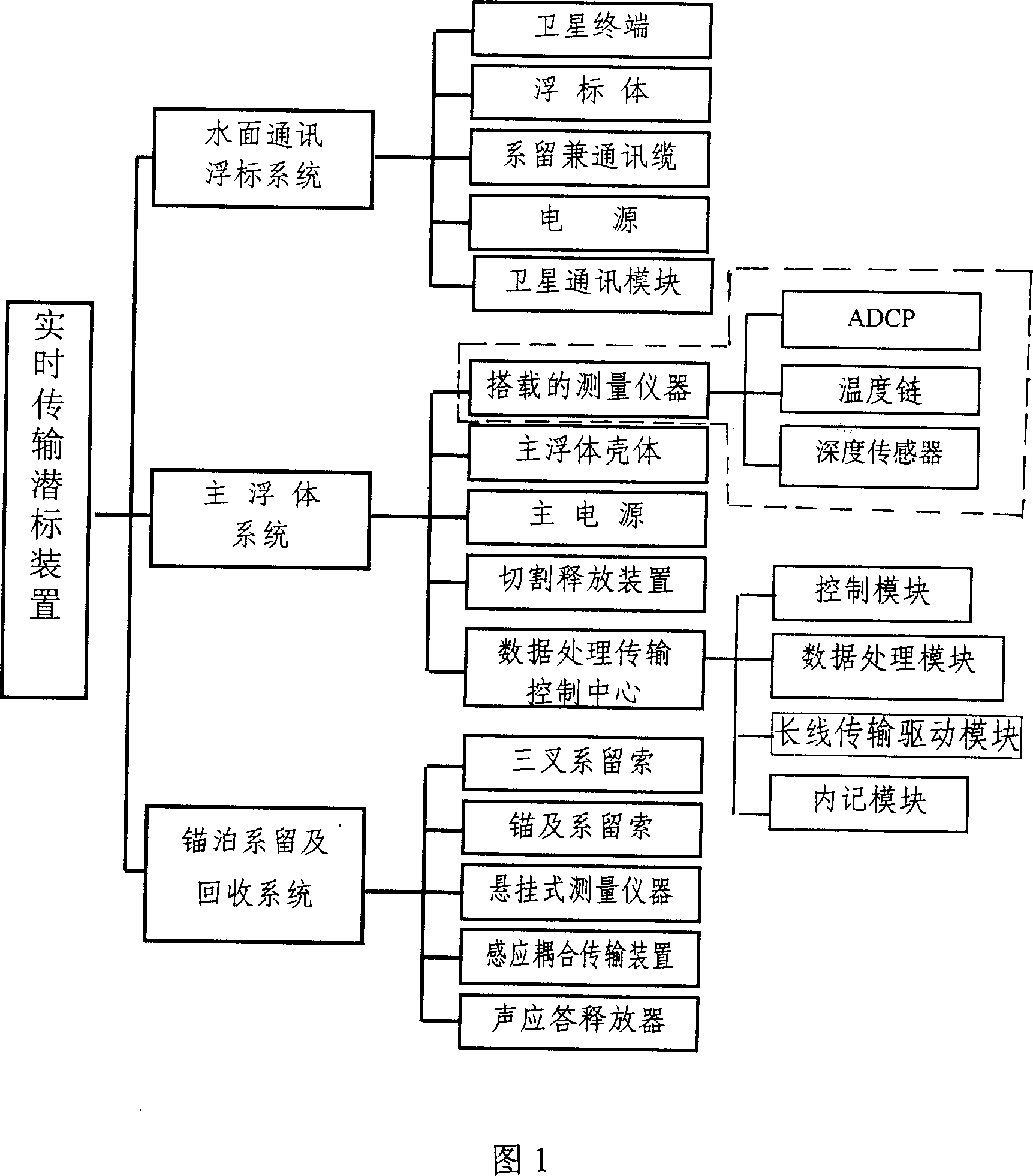
[0039] Fig. 7 is a schematic diagram of the structural arrangement of an example of the present invention and a schematic diagram of the use of this example in a sea area of ​​4000 meters. This example includes (a) main buoy system, (b) surface buoy system, (c) mooring mooring and recovery system.

[0040] (a) The main floating body system consists of a pressure-resistant main floating body shell 1, a main power supply 9 that can work continuously for 210 days, a connecting cable group 10, a data processing transmission control center 20, and a trident mooring rope 19 made of plastic-coated steel cables.

[0041](b) The surface buoy system is mainly made of reinforced glass fiber reinforced plastic fiber, which can withstand pressure of 4.5MPa and has a displacement of 26L. The surface buoy shell 3 adopts the communication terminal 4 of the INMARSAT-C maritime communication satellite system TT-3026L / M, and the length is 400 meters. Kevlar core mooring and communication cable 2...


PUM


Abstract

The invention relates to a real-time transmission undersea buoy device, to timely solve that the data measured in the water by the undersea buoy is transmitted to a shore station, and the marine observed data and information can be obtained without recovery, (a) the main floating body system (b) anchored mooring and recovery system, and (c) the surface buoy system. The invention solves that marine measured data cannot be obtained in a timely manner in the past.

Description

field of invention [0001] The invention relates to a submersible buoy device, in particular to a submersible buoy device which realizes real-time data transmission through a surface buoy equipped with a satellite communication terminal. Background technique [0002] The submersible buoy is an important technical equipment for obtaining marine environmental data. Since the submersible buoy device can carry a variety of detection and measurement instruments, it can carry out long-term, fixed-point, continuous, and multi-level synchronous measurements in a relatively concealed manner under harsh sea conditions. It has been widely used in marine scientific research and marine military reconnaissance. According to reports, the marine environmental data acquired by the US submersible system account for more than 30% of its total marine data. [0003] At present, the observation data of submersible buoy devices at home and abroad are mainly stored in self-c...

Claims


Application Information

Patent Timeline
IPC IPC(8): G08C19/00G01C13/00
Inventor 张云海邓国新胡书仿张选明陈焕杰谷军邓秀华李锋严建洪吴旌郭晋兵任翀涂疑熊志奇孙善春徐劲松
Owner 710TH RES INST OF CHINA SHIPBUILDING IND CORP
Why Eureka
Try Eureka