Electrical plug connector and electrical plug connection

一种插塞连接器、连接电缆的技术,应用在连接、电气元件、连接装置的零部件等方向,能够解决不再保持密封作用、扣紧力矩大、电气插塞连接器损坏等问题,达到防止过度挤压的效果

一种插塞连接器、连接电缆的技术,应用在连接、电气元件、连接装置的零部件等方向,能够解决不再保持密封作用、扣紧力矩大、电气插塞连接器损坏等问题,达到防止过度挤压的效果

CN1972024AActive Publication Date: 2007-05-30IMF ELECTRONIC GMBH

Image

  • Electrical plug connector and electrical plug connection
  • Electrical plug connector and electrical plug connection
  • Electrical plug connector and electrical plug connection

Examples


Embodiment Construction

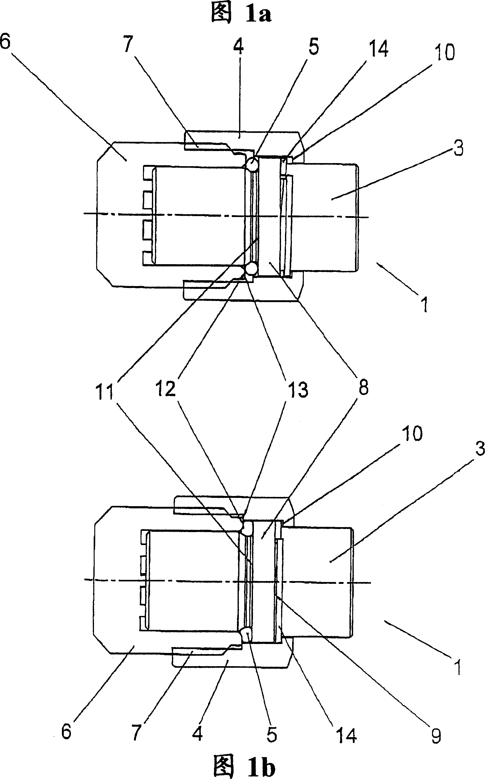
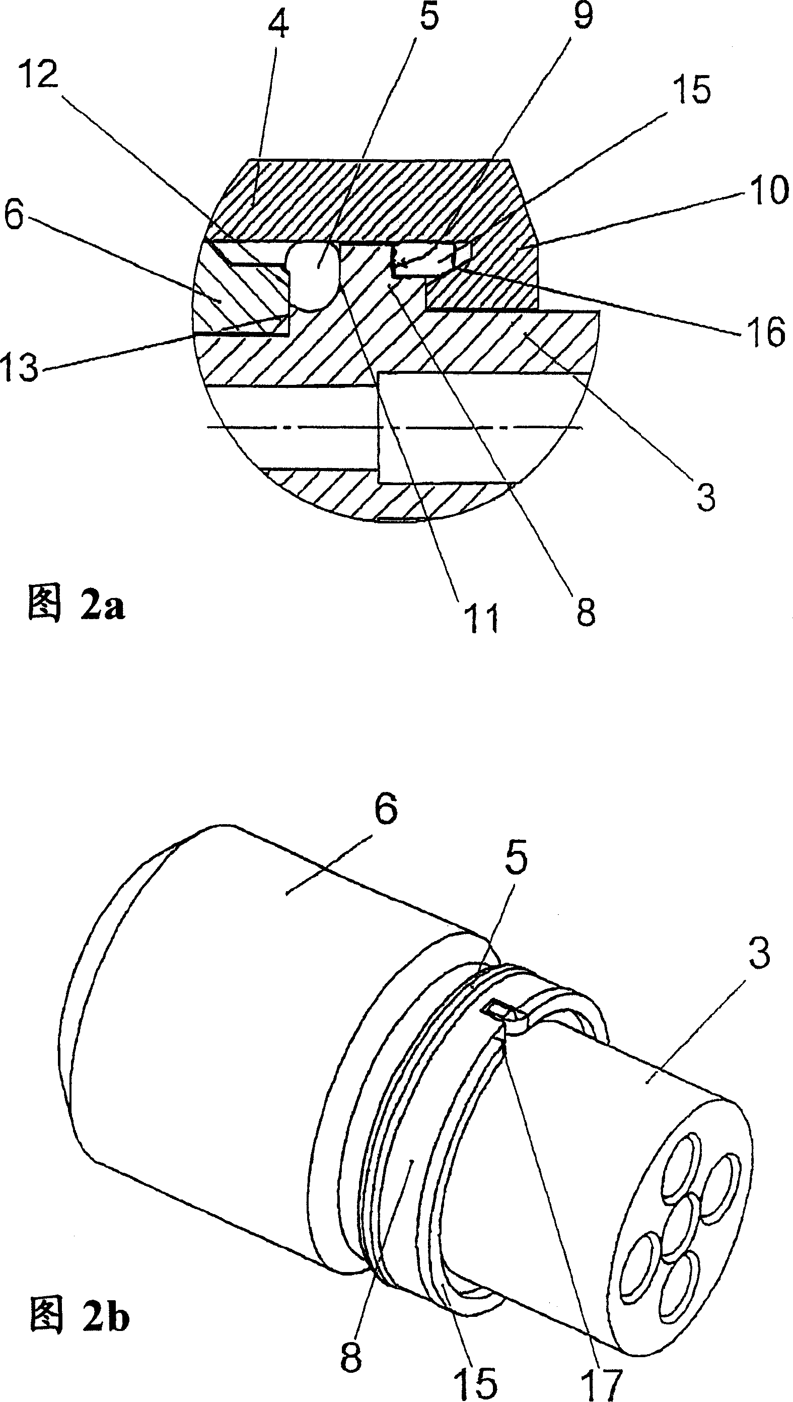
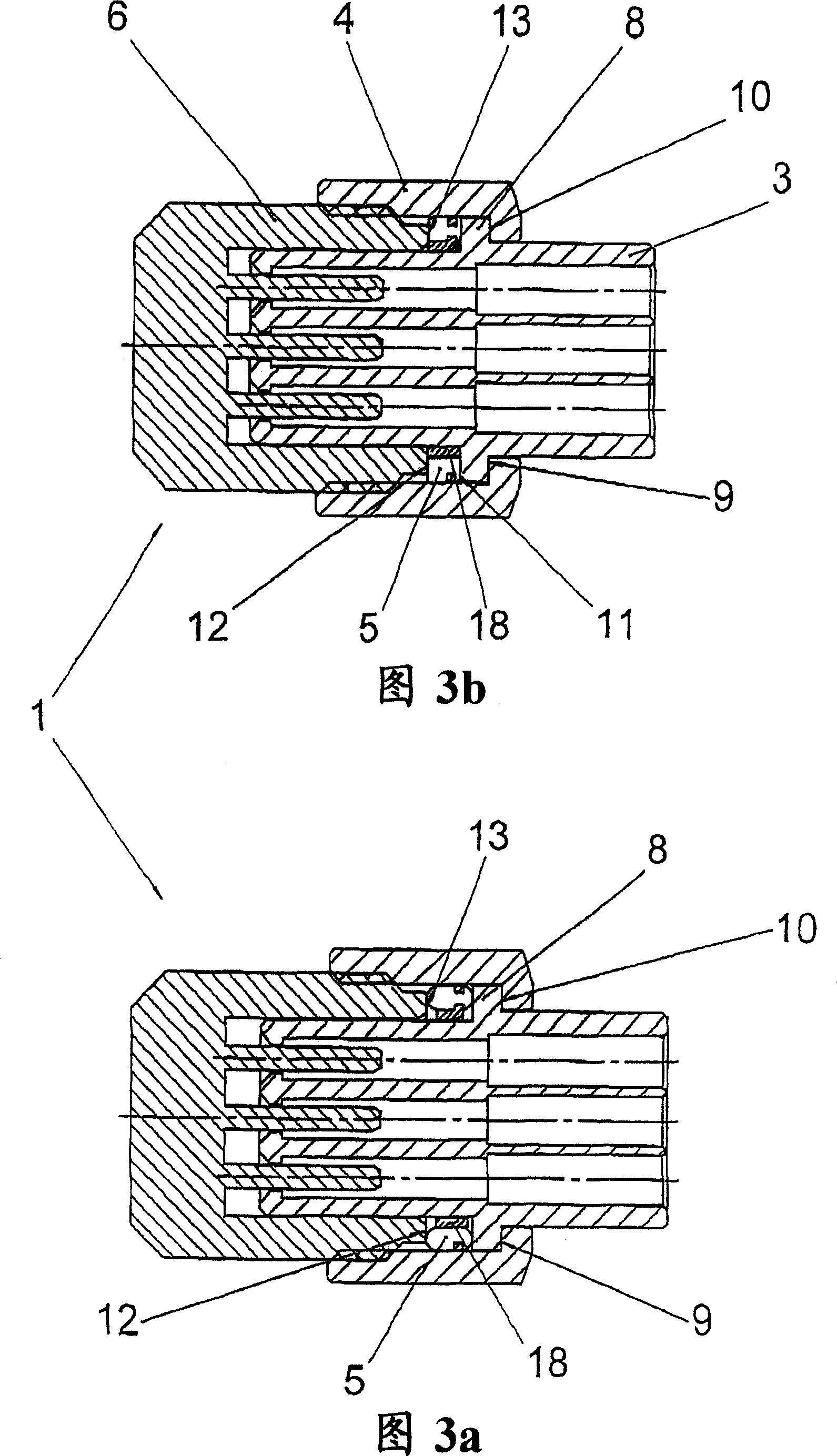
[0036] The figures show different configurations of an electrical plug-in connector 1 or rather individual components of such an electrical plug-in connector 1 . Such an electrical plug connector 1 has a handle 2 ( FIG. 12 ) enclosing a connecting cable not shown here, and a contact support 3 is arranged on the contact support 3 in a rotatable and limited axially displaceable manner. The locking nut 4, and the elastic seal 5 arranged on the contact support 3 in the form of a sealing ring. At the same time, since the electrical plug connector 1 can be connected to its corresponding mating plug connector 6 , the lock nut 4 is screwed onto the thread 7 formed on the outer sleeve of the mating plug connector 6 .

[0037] As can be seen from FIGS. 1 to 7 , the contact carrier 3 has a circumferential collar 8 which is located approximately in the middle region of the contact carrier 3 . The surrounding flange 8 has a first end face 9 which serves as a stop for a shoulder 10 at the ...


PUM


Abstract

An electrical plug connector comprising a handle (2) enclosing a connecting cable, a contact support (3), and a lock nut rotatably and limitedly movable axially arranged on the contact support (3) (4) and the elastic seal (5) arranged on the contact support (3), wherein the lock nut (4) can be screwed on the thread (7) formed on the outer sleeve of the butt plug connector (6) , and wherein the contact support (3) has a surrounding flange (8), its first end face (9) is used as a stop for the shoulder (10) at the end of the lock nut (4), and its orientation is toward the abutment The second end surface (11) of the plug connector (6) is used as a stopper for the seal (5), wherein the seal (5) is assembled between the plug connector (1) and the mating plug connector (6). It is arranged between the flange (8) of the contact carrier (3) and the mating plug connector (6), in particular its end face (12), in order to press the seal (5).

Description

technical field [0001] The invention relates to an electrical plug connector comprising a handle surrounding a connecting cable, a contact support, a lock nut arranged rotatably and limitedly movable axially on the contact support and arranged on Elastomeric seal on a contact support, in which a lock nut can be screwed onto a thread formed on the outer sleeve of a mating plug connector, and in which the contact support has a surrounding flange, the first end face of which acts as a lock The limit of the shoulder of the end of the tight nut, and its second end face towards the mating plug connector is used as the limit of the seal, wherein the seal is in the assembled state of the plug connector and the mating plug connector , between the flange of the contact carrier and the mating plug connector, in particular its end face, so arranged that the seal is compressed. Furthermore, the invention relates to an electrical plug-in connection with a plug-in connector and a mating plu...

Claims


Application Information

Patent Timeline
30 May 2007
Publication
CN1972024A
IPC
H01R13/533; H01R13/623
CPC
H01R13/622; H01R13/5219
Inventors
W·默赫纳特; B·弗罗塞