Bending machine for steel bars for construction and bending method thereof

A bending machine and construction technology, applied in the direction of metal processing equipment, metal processing, manufacturing tools, etc., can solve the problems of hard to determine, easily damaged steel bars at the bend, and reduced toughness, so as to avoid post-cutting, Bending is convenient and fast, and the effect of preventing excessive extrusion

Active Publication Date: 2020-04-07
CHINA RAILWAY 12TH BUREAU GRP +1
View PDF7 Cites 2 Cited by
  • Summary
  • Abstract
  • Description
  • Claims
  • Application Information

AI Technical Summary

Problems solved by technology

[0002] Steel bars are the most consumed building materials on construction sites. Construction steel bars usually cannot be used directly. They usually need to be bent and then connected and poured into concrete as a supporting structure. Bending of steel bars usually requires a steel bar bending machine. Existing Most of the advanced steel bar bending machines directly bend the steel bars. After direct bending, the corners at the bends are easy to damage the steel bars and reduce their toughness. It is cumbersome and complicated, and it is not easy to determine the bending angle and needs to be improved

Method used


Image

  • Bending machine for steel bars for construction and bending method thereof
  • Bending machine for steel bars for construction and bending method thereof
  • Bending machine for steel bars for construction and bending method thereof

Examples


Embodiment Construction

[0026] Below in conjunction with accompanying drawing and specific embodiment the present invention is described in further detail:

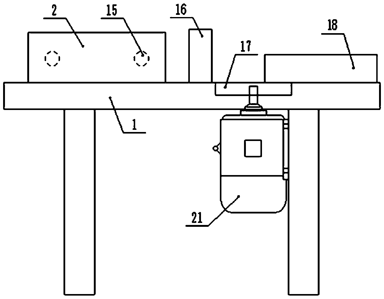
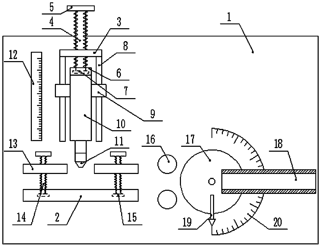
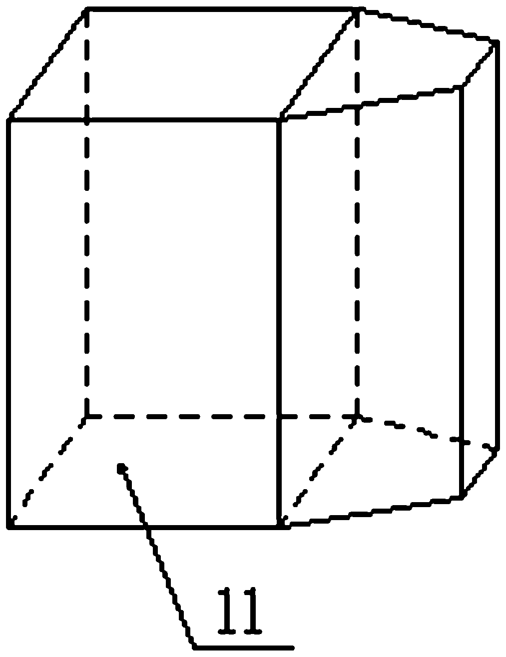
[0027] Such as figure 1 , figure 2 , image 3 The shown steel bar bending machine for construction includes an operation console 1, on which a baffle plate 2 and a fixed plate 3 are fixed, the positions of the baffle plate 2 and the fixed plate 3 are corresponding and parallel to each other, and the middle of the fixed plate 3 is threaded. There is a threaded rod A4, the two ends of the fixed plate 3 are vertically fixed with a fixed rod 8, one end of the threaded rod A4 is fixed with a handle 5, and the other end is fixed with a rotating disk A7, and the fixed rod 8 is covered with a sleeve 9 slidingly connected with it. 9 is fixed with a hydraulic rod 10, and a connecting block 6 is fixed on the hydraulic rod 10. The connecting block 6 is connected with a rotating disk A7 in rotation, and a trapezoidal block 11 is fixed on the top of the hy...


PUM

PropertyMeasurementUnit
thicknessaaaaaaaaaa
lengthaaaaaaaaaa

Abstract

The invention discloses a construction reinforcing steel bar bending machine and a bending method thereof. The construction reinforcing steel bar bending machine comprises an operating table which isfixedly provided with a baffle and a fixing plate. A threaded rod A is arranged in the middle of the fixing plate, and fixing rods are arranged at the two ends of the fixing plate. A handle and a rotating disk A are fixedly arranged on the threaded rod A, sleeves are arranged on the fixing rods, and a hydraulic rod is arranged between the sleeves. A connecting block is arranged on the hydraulic rod, and the rotating disk A is arranged in the connecting block. A trapezoid block is arranged on the hydraulic rod, and a dividing rule is fixed to the operating table. Clamping plates are arranged atthe two ends of the trapezoid block, and rotating disks B are arranged at the two ends of the baffle. The rotating disks B are fixedly provided with threaded rods B, and the threaded rods B are in threaded connection with the clamping plates. The operating table is fixedly provided with a fixing block, and a circular plate is arranged on the operating table. A steel tube is arranged on the circular plate, and a protractor is arranged on the edge of the circular plate. A pointer is fixed on the circular plate, and a speed reducing motor is arranged at the lower end of the operating table to adjust the hydraulic rod and prevent the hydraulic rod from being extruded too much. The damage to reinforcing steel bars is small when the reinforcing steel bars are bent after being flattened, bendingafter flattening is convenient and quick, the bending position is precise through the protractor, and the trouble of later cutting is saved.

Description

technical field [0001] The invention relates to the field of construction, in particular to a steel bar bending machine for construction and a bending method thereof. Background technique [0002] Steel bars are the most consumed building materials on construction sites. Construction steel bars usually cannot be used directly. They usually need to be bent and then connected and poured into concrete as a supporting structure. Bending of steel bars usually requires a steel bar bending machine. Existing Most of the advanced steel bar bending machines directly bend the steel bars. After direct bending, the corners at the bends are easy to damage the steel bars and reduce their toughness. It is cumbersome and complicated, and it is not easy to determine the bending angle and needs to be improved. Contents of the invention [0003] In order to solve the above existing problems, the present invention provides a steel bar bending machine for construction and a bending method ther...

Claims


Application Information

Patent Timeline
Patent Type & Authority Patents(China)
IPC IPC(8): B21F1/00B21F5/00B21C51/00
CPCB21C51/00B21F1/00B21F5/00
Inventor 陈玉达崔新芳沈阔王自虎韩金波
Owner CHINA RAILWAY 12TH BUREAU GRP
Why Eureka
Try Eureka