Eureka AIR delivers breakthrough ideas for toughest innovation challenges, trusted by R&D personnel around the world.

Cyclonic separator for vacuum cleaner

A technology of cyclone separation device and cyclone separator, which is applied in the direction of suction filter, etc., can solve the problems of limited cyclone space, reduced dust separation efficiency, and high noise, and achieve the effects of reducing flow speed, increasing air capacity, and improving proportional size

Active Publication Date: 2010-05-19
ECOVACS ROBOTICS (SUZHOU ) CO LTD
View PDF1 Cites 0 Cited by
  • Summary
  • Abstract
  • Description
  • Claims
  • Application Information

AI Technical Summary

Problems solved by technology

[0002] The secondary cyclone part in the existing cyclone dust bucket is an inverted cone. When the inverted cone structure is used, its proportional size is difficult to meet the requirements of the large flow rate of the existing vacuum cleaner.
If the conical body structure is used in such a large air flow, the cyclone space is limited, and the noise is relatively large during the cyclone
Moreover, the dust collection bucket is easy to fill up. If the dust collection bucket is not emptied in time, the dust in the dust collection bucket will rotate with the air, so the efficiency of separating dust will be greatly reduced, so the length of the barrel of a general inverted cone will be Difficult to meet the needs of household vacuum cleaners

Method used


Image

  • Cyclonic separator for vacuum cleaner
  • Cyclonic separator for vacuum cleaner
  • Cyclonic separator for vacuum cleaner

Examples


Embodiment Construction

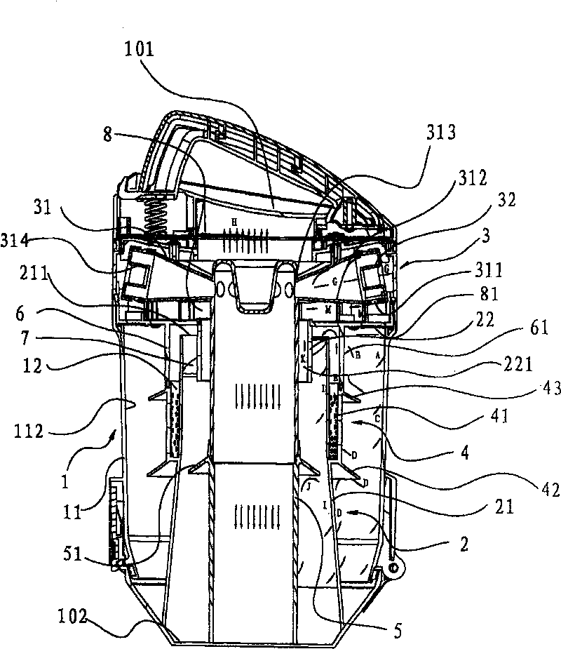
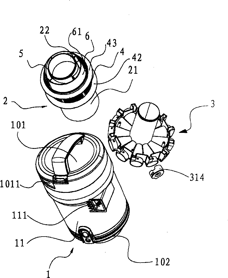
[0028] Such as figure 1 and figure 2 The shown cyclone separation device of a vacuum cleaner has a primary cyclone separator 1 located upstream, a secondary cyclone separator 2 located downstream of the primary cyclone separator 1, and a tertiary cyclone separator located at the secondary cyclone separator 2 3.

[0029] The first-stage cyclone separator 1 has a first-stage cyclone barrel 11, and the side wall of the first-stage cyclone barrel 11 is provided with a first-stage air inlet 111, and the air flow with dust enters the first-stage cyclone barrel 11 from here, and the first-stage air inlet 111 is opposite The inner wall of the primary cyclone barrel 11 is arranged tangentially, so that the air entering from the primary air inlet 111 enters the primary cyclone barrel 11 in a direction tangential to the side wall, so that the air inside the primary cyclone separator 1 Create a vortex.

[0030] The secondary cyclone separator 2 has a secondary cyclone barrel 21, the i...


PUM


Abstract

The cyclonic separator for vacuum cleaner includes at least one primary cyclonic separator in the upstream and one secondary cyclonic separator in the downstream, and each of the primary cyclonic separator and the secondary cyclonic separator includes one cyclonic tub with air inlet in the wall and one guide body inside the cyclonic tub. Airflow entering the cyclonic tub forms a rotating airflow in gradually increased rotating radius at least partially. The present invention has increased air volume inside the cyclonic tub, increased dust collector volume, reduced dust collecting noise and improved cyclonic structure, and is suitable for household vacuum cleaner.

Description

technical field [0001] The invention relates to a cyclone separation device of a vacuum cleaner. Background technique [0002] The secondary cyclone part in the existing cyclone dust bucket all adopts an inverted cone structure. When the inverted cone structure is adopted, its proportional size is difficult to meet the large flow requirement of the existing vacuum cleaner. If the conical body structure is used under the condition of such a large air flow, the cyclone space is limited, and the noise is relatively large during the cyclone. Moreover, the dust collection bucket is easy to fill up. If the dust collection bucket is not emptied in time, the dust in the dust collection bucket will rotate with the air, so the efficiency of separating dust will be greatly reduced, so the length of the barrel of a general inverted cone will be It is difficult to meet the needs of household vacuum cleaners. Contents of the invention [0003] The object of the present invention is to...

Claims


Application Information

Patent Timeline
Patent Type & Authority Patents(China)
IPC IPC(8): A47L9/16
Inventor 周红波
Owner ECOVACS ROBOTICS (SUZHOU ) CO LTD
Why Eureka
Eureka Blog
Learn More