Self-cleaning pipeline filtering device for water conservancy project

A technology for water conservancy projects and filtration devices, applied in filtration and separation, fixed filter element filters, separation methods, etc., can solve problems such as troublesome use, inability to automatically clean and discharge impurities, manual disassembly and cleaning, etc., to reduce costs and increase convenience. the effect of avoiding waste

Active Publication Date: 2020-06-02
郭新生
View PDF5 Cites 14 Cited by
  • Summary
  • Abstract
  • Description
  • Claims
  • Application Information

AI Technical Summary

Problems solved by technology

[0004] The purpose of the present invention is to solve the disadvantages in the prior art that it cannot automatically clean and discharge impurities, requires manual disassembly and cleaning, and is troublesome to use, and proposes a self-cleaning pipeline filter device for water conservancy projects

Method used


Image

  • Self-cleaning pipeline filtering device for water conservancy project
  • Self-cleaning pipeline filtering device for water conservancy project

Examples


Embodiment 1

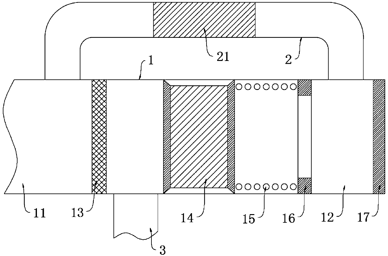
[0024] refer to figure 1 , a self-cleaning pipeline filter device for water conservancy projects, comprising a filter pipe 1, the filter pipe 1 includes a water inlet 11 and a sewage outlet 12, a slag discharge pipe 2 is installed on the side wall of the filter pipe 1, and a slag discharge pipe 2 is installed on the slag discharge pipe 2 A pressure valve 21, a filter screen 13 and a fixed ring 16 are installed on the inner wall of the filter pipe 1, and the filter screen 13 and the fixed ring 16 are both located between the two joints of the slag discharge pipe 2 and the filter pipe 1, and the fixed ring 16 is close to One end of filter screen 13 is equipped with spring 15, and spring 15 is equipped with piston 14 near one end of filter screen 13, and clear water pipe 3 is installed on the side wall of filter pipe 1, and sewage outlet 12 plugs are provided with pressure plug 17.

[0025] The clean water pipe 3 is located on the right side of the strainer 13, and the diameter o...

Embodiment 2

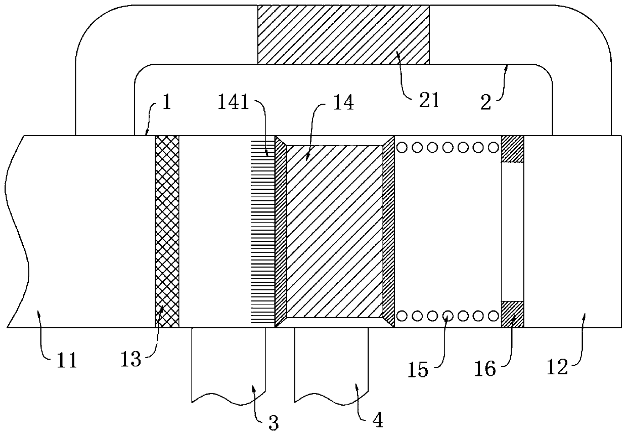
[0032] refer to figure 2 , a self-cleaning pipeline filter device for water conservancy projects, which is basically consistent with Embodiment 1, the difference is that:

[0033] The sewage outlet 12 is closed, the filter pipe 1 is located on one side of the clean water pipe 3 and a sewage pipe 4 is installed, and the diameter of the sewage pipe 4 is smaller than the length of the piston 14, and the length of the piston 14 is greater than the farthest distance from the filter screen 13 to the clean water pipe 3 And less than the shortest distance from the filter screen 13 to the sewage pipe 4, the end of the piston 14 near the filter screen 13 is equipped with a plurality of needles 141;

[0034]When the filter screen 13 is blocked by impurities, the water flows along the slag discharge pipe 2 to the sewage outlet 12. Since the sewage outlet 12 is closed, the water flow reverses in the filter pipe 1 to push the piston 14 to move to the filter screen 13 and open the sewage pi...


PUM


Abstract

The invention discloses a self-cleaning pipeline filtering device for a water conservancy project. The filtering device comprises a filter pipe, the filter pipe comprises a water inlet and a sewage port, a residue discharging pipe is mounted on the side wall of the filter pipe, a pressure valve is mounted on the residue discharging pipe, a filter screen and a fixing ring are mounted on the inner wall of the filter pipe, the filter screen and the fixing ring are both located between the two connecting positions of the residue discharging pipe and the filter pipe, a spring is mounted at the end,close to the filter screen, of the fixing ring, a piston is mounted at the end, close to the filter screen, of the spring, and a clear water pipe is mounted on the side wall of the filter pipe. The pressure of the residue discharging pipe is higher than that of the filter pipe after the filter screen is blocked, so that water flows along the residue discharging pipe to form negative pressure to peel off impurities on the filter screen; the clean water pipe is blocked through the piston to prevent sewage from entering, the clear water pipe and a blow-off pipe are arranged side by side, the clear water pipe can be closed to open the blow-off pipe to achieve self-cleaning when the filter screen is blocked, the self-cleaning speed is further increased through a pricking needle, and water resources are saved.

Description

technical field [0001] The invention relates to the field of water conservancy engineering, in particular to a self-cleaning pipeline filter device for water conservancy engineering. Background technique [0002] In water conservancy projects, water conservancy pipelines transport relatively clean water flow into various areas, while the water flow at the inlet of water conservancy pipelines is dirty, so preliminary filtration of water flow is required. [0003] The existing pipeline is filtered by installing a filter tube with a filter screen on the pipeline. The impurities in the water are filtered by the filter screen. The pressure is low, and the water end cannot be used normally. It is necessary to manually disassemble the filter tube to clean up impurities before installation and use, which is more troublesome to use. Contents of the invention [0004] The purpose of the present invention is to solve the disadvantages in the prior art that the impurity cannot be aut...

Claims


Application Information

Patent Timeline
Patent Type & Authority Applications(China)
IPC IPC(8): B01D29/03B01D29/64B01D29/94B01D35/02
CPCB01D29/03B01D29/64B01D29/94B01D35/02
Inventor 郭新生
Owner 郭新生
Why Eureka
Try Eureka