

Fluid machine
A fluid machinery and impeller technology, which can be used in mechanical equipment, liquid fuel engines, components of pumping devices for elastic fluids, etc., and can solve problems such as increasing the manufacturing cost of fluid machinery.
- Summary
- Abstract
- Description
- Claims
- Application Information
AI Technical Summary
Problems solved by technology
Method used
Image

Examples
Embodiment Construction
[0018] Hereinafter, embodiments of the present invention will be described in detail with reference to the drawings. In the drawings, common reference numerals are attached to the same or similar constituent elements.
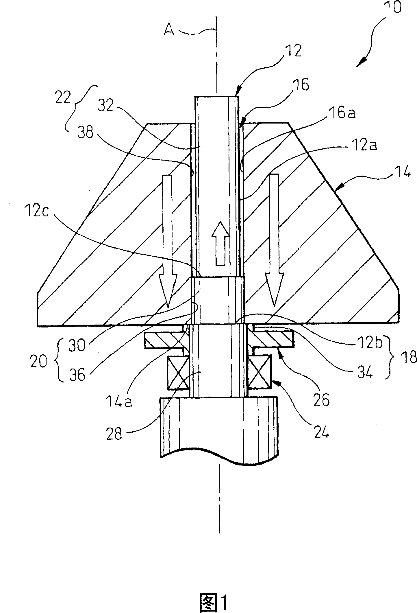
[0019] Referring to the drawings, FIG. 1 shows a shaft 12 and an impeller 14 of a fluid machine 10 according to an embodiment of the present invention. The fluid machine 10 of the illustrated embodiment is a machine having a structure of a centrifugal blower, and well-known structures can be used for the structure of the blades of the impeller 14 and the structure of the casing (not shown), so description thereof will be omitted. In addition, the present invention is not limited to the centrifugal blower, and can be applied to other various fluid machines.
[0020] The fluid machine 10 includes a shaft 12 and an impeller 14 having a shaft hole 16 inserted into the shaft 12 , and has a structure in which the impeller 14 is coupled to the shaft 12 by interferenc...
PUM
 Abstract
Description
Claims
Application Information