Device for air cleaning

A technology of air purification equipment and filters, applied in the direction of steam flow control, chemical instruments and methods, external electrostatic separators, etc., can solve the problems of reduced overall efficiency and high cost

Active Publication Date: 2007-06-13
DARWIN TECH
View PDF1 Cites 15 Cited by
  • Summary
  • Abstract
  • Description
  • Claims
  • Application Information

AI Technical Summary

Problems solved by technology

When done correctly, the corona wire achieves good initial charging along its length, but not at the ends where it must be attached to the support frame
The air flowing over the end of the wire is not effectively charged and this leads to a reduction in overall efficiency
Also, for high efficiency, relatively large currents are required to be supplied to the corona wires, resulting in high ozone levels and costly power supplies

Method used


Image

  • Device for air cleaning
  • Device for air cleaning
  • Device for air cleaning

Examples


Embodiment Construction

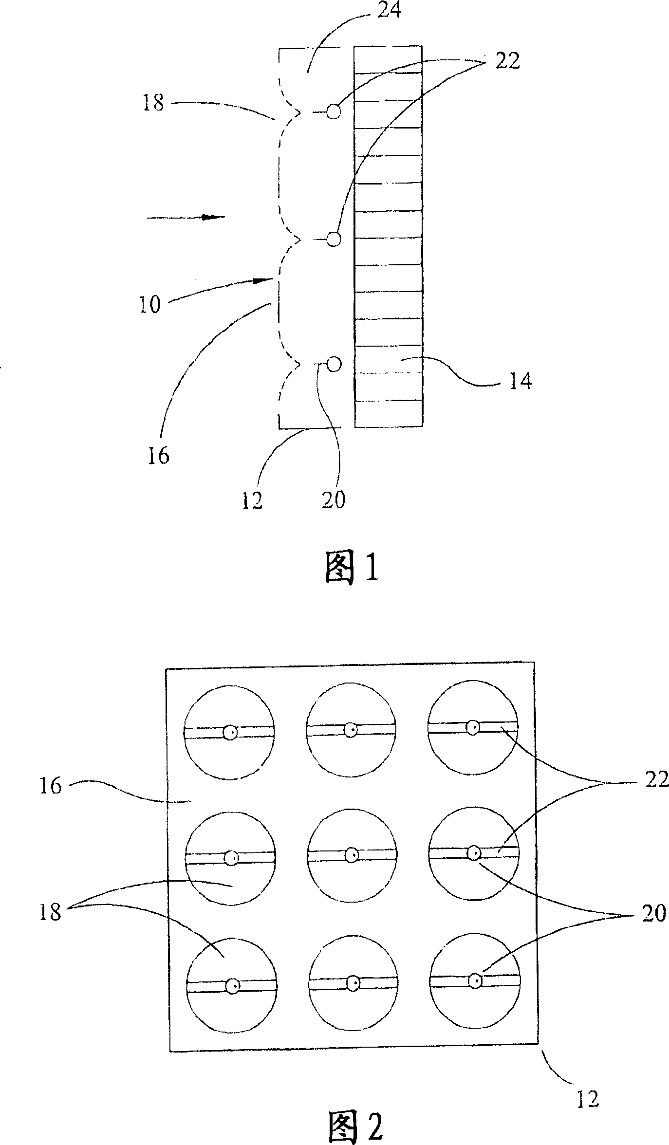
[0025] Referring to Figures 1 and 2 of the drawings, an air cleaning device 10 includes a particle charging zone 12 and a filter 14 . The particle charging area 12 comprises a grounded conductive plate 16 with apertures 18 through which air is drawn or blown in in the direction of the arrow.

[0026] Behind each circular aperture 18 there is located a centrally arranged corona emitter pin 20 , which is supported on a conductive rod 22 and is at high voltage with respect to the conductive plate 16 which is normally at ground potential. A stream of air ions 24 (shown in dashed lines) generated by the emitter pin 20 moves towards the conductive plate 16 under the action of the electric field. The ions 24 spread out in a conical distribution from the ends of the emitter pins 20 and they are substantially all deposited on the conductive plate 16 and more particularly near the circumference around each circular aperture 18 .

[0027] The combination of particle charging region 12, ...


PUM


Abstract

An air cleaning device (10) has a particle charging zone (12) comprising a conducting sheet (16) having a plurality of apertures (18), through which air can be passed, and a plurality of corona emitters (22) each associated with an aperture, and a filter (14).

Description

technical field [0001] The present invention relates to improvements in air cleaning devices and to air cleaning devices. Background technique [0002] The usual method of purifying particulate matter from the air is to pass the air over a particle-charged array of corona wires and grounded plates and subsequently deposit the charged particles in the electric field, usually onto an array of metal plates alternately placed at high and ground potentials . Such devices are commonly referred to as electrostatic precipitators. [0003] Conventional electrostatic precipitators have many disadvantages. For high efficiency, the corona charging wires must be placed carefully and centrally to ensure uniform charging of the particles. These wires quickly collect dust on the wire surface, reducing the corona charging current and creating an uneven corona, resulting in reduced efficiency. When cleaning corona wires, they often bend or move out of alignment due to their brittle nature...

Claims


Application Information

Patent Timeline
Patent Type & Authority Applications(China)
IPC IPC(8): B03C3/011B03C3/36
CPCB03C3/011B03C3/36B03C3/08B03C3/12B03C3/41B03C3/47B03C2201/10
Inventor 乔治·格里菲斯杰弗里·N·W·盖伊
Owner DARWIN TECH
Why Eureka
Try Eureka