Particle separator

A particle separator and particle technology, applied in the direction of dispersed particle separation, separation method, chemical instrument and method, etc., can solve the problem of low separation rate

Inactive Publication Date: 2007-07-11
EISENMANN CORP
View PDF0 Cites 2 Cited by
  • Summary
  • Abstract
  • Description
  • Claims
  • Application Information

AI Technical Summary

Problems solved by technology

Gravity flight separators can be realized and operated without large process costs, but have a low separation rate compared to cyclone separators

Method used


Image

  • Particle separator
  • Particle separator

Examples


Embodiment Construction

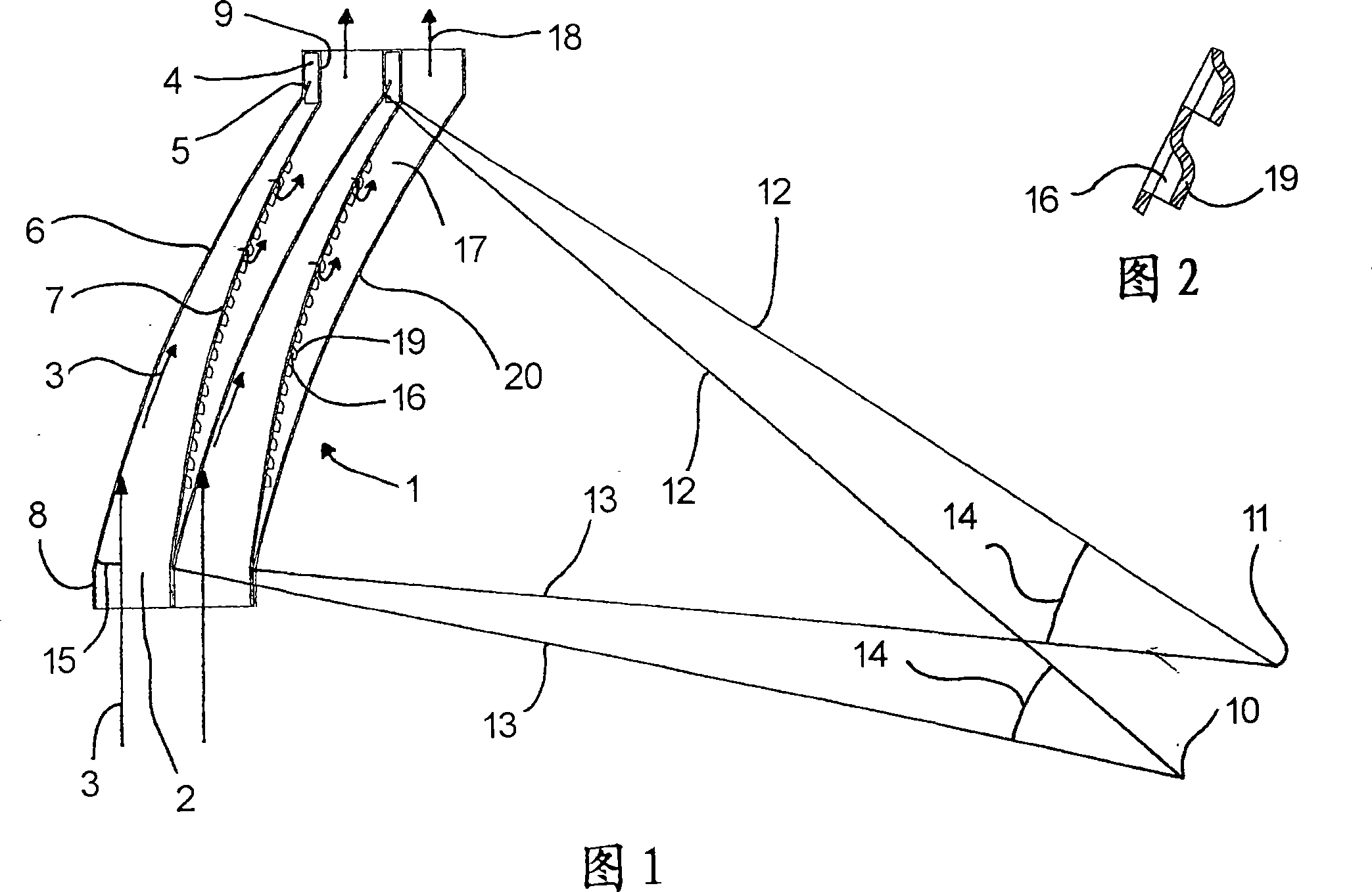
[0027] The particle separator shown in FIG. 1 and indicated generally by the reference number 1 for an air supply (not shown) has two substantially identical, parallel to each other, for the particle-contaminated air flow 3. Input channel 2.

[0028] The inlet channel 2 narrows gradually in the direction of the incoming polluted gas flow 3 . The inlet channels each open into an outlet channel 4 for the particles.

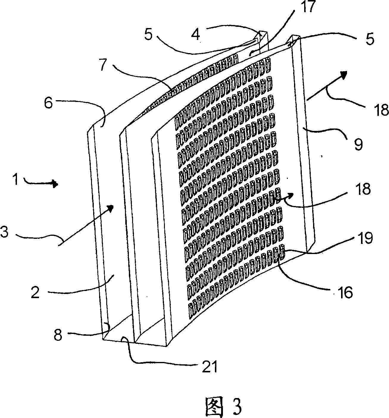
[0029] Furthermore, in the region of the outlet channel 4 in which the respective inlet channel 2 opens, a retaining unit 5 for the particles is realized in each case from a planar sheet metal, by means of which the particles are prevented from flowing back into the respective inlet channel 2 .

[0030] The input channels 2 are respectively bounded by air-guiding surfaces, ie an outer air-guiding plate 6 and an inner air-guiding plate 7 . The outer air deflectors 6 are respectively bent towards the inside of the inlet channel 2 , that is, convex when viewed from t...


PUM


Abstract

A particle separator (1) is disclosed, in particular, for an air inlet unit, comprising at least one inlet channel (2) , for a fluid flow (3), contaminated with particles, in particular a contaminated air flow, defined between two opposing fluid guide surfaces (6, 7), narrowing in the fluid flow direction and opening in an outlet channel (4) for particles, connected to at least one fluid channel (16) for the purified fluid (18) which leads away from the inlet channel (2) in a region (17) outside the inlet channel (2). Furthermore, a method for the purification of the fluid flow (3) contaminated with particles is disclosed. According to the invention, the fluid flow (3) contaminated with particles may be efficiently purified with a high degree of separation with a low pressure loss, whereby the above is led along one of the fluid guide surfaces (6), which is curved, at least in a part before the outlet channel (4), towards the interior of the inlet channel (2).

Description

technical field [0001] The invention relates to a particle separator, in particular for an air supply device, which has at least one supply channel for a fluid flow contaminated by particles, in particular a polluted gas flow, which is formed by two oppositely arranged guides. The flow surface is defined, narrows gradually in the direction of fluid flow and opens into an outlet channel for the particles, the input channel is connected to at least one fluid channel for the purified fluid, the fluid channel leads away from the input channel to the outside of the input channel within the area. [0002] Furthermore, the invention relates to a method for purifying a fluid flow, in particular a polluted gas flow, contaminated by particles, in which the fluid flow is fed into at least one inlet channel which gradually narrows along the original fluid flow direction, the inlet The channel opens into an exhaust channel for the particles, and the purified fluid is directed out of the i...

Claims


Application Information

Patent Timeline
Patent Type & Authority Applications(China)
IPC IPC(8): B01D45/16
CPCB01D45/16B01D45/02
Inventor A·卡特菲迪斯
Owner EISENMANN CORP
Why Eureka
Try Eureka