End effector structure for stapling apparatus

a stapling apparatus and end effector technology, applied in the field of surgical staplers, can solve the problems of reducing the quality of stapling, so as to reduce or prevent the bleeding of staple lines and cutting lines. , the effect of increasing the seal quality and strength

Active Publication Date: 2018-06-26
EXPANDOHEAT
View PDF8 Cites 110 Cited by
  • Summary
  • Abstract
  • Description
  • Claims
  • Application Information

AI Technical Summary

Benefits of technology

The invention is about an instrument that combines both stapling and heating techniques to stop blood flow during surgery. It works by using thermal energy and staples to join together different parts of tissue. This helps improve the overall strength of the area around the staple lines and reduces bleeding from those areas. Overall, this device makes surgeries safer and more effective with better outcomes.

Problems solved by technology

This patent describes a technical problem in surgery where there are times when we need to stop bleeding quickly without causing damage to the patient's tissues. Current methods like laser treatment or chemical agents used to clot blood take too much time or risk damaging the surrounding areas. There is a new method called thermocompression that uses high temperatures to change how certain proteins behave in the tissue, but current tools don't work well enough yet. So, there is a need for a tool that combines both the benefits of traditional stapling and quick heating through the use of electrical currents.

Method used


Image

  • End effector structure for stapling apparatus
  • End effector structure for stapling apparatus
  • End effector structure for stapling apparatus

Examples


second embodiment

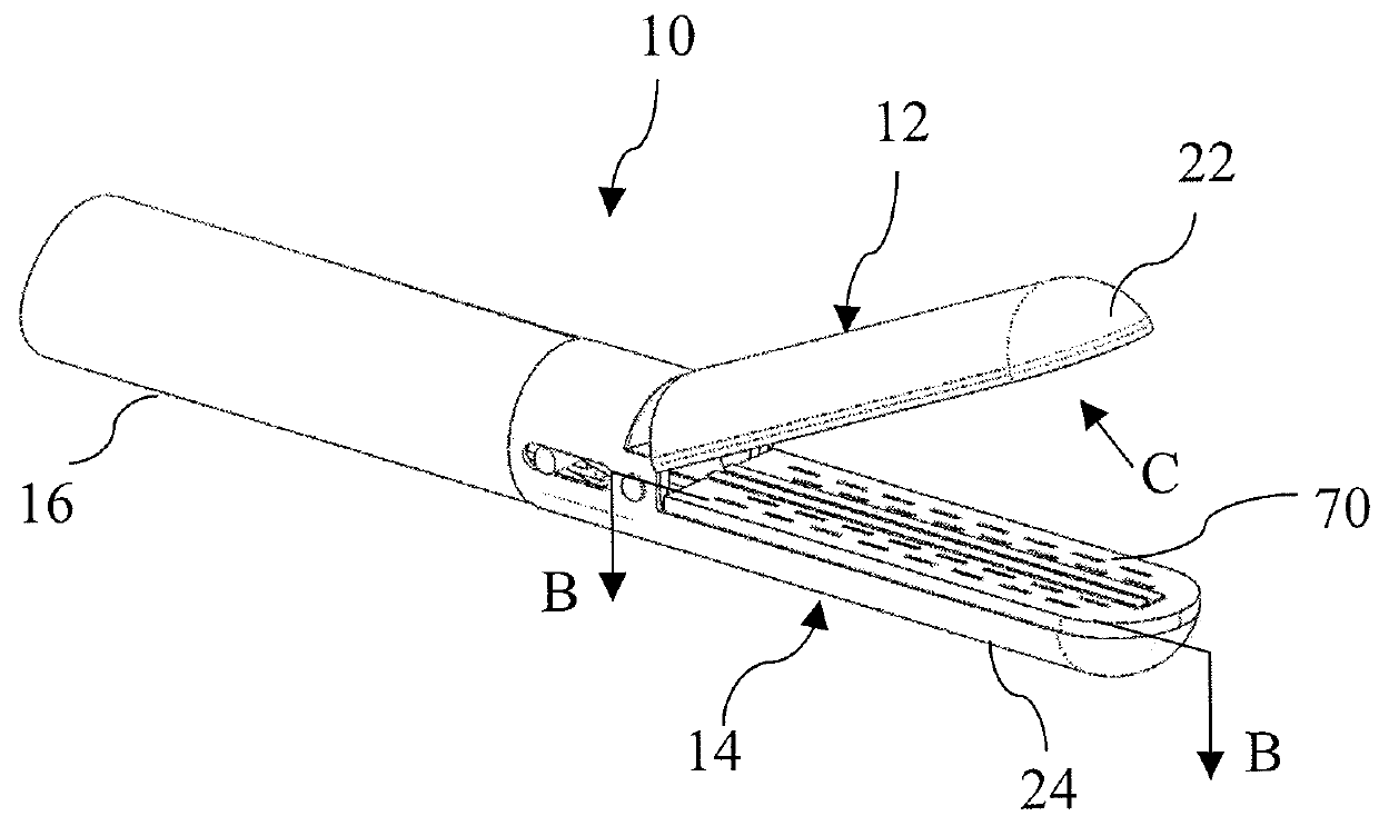
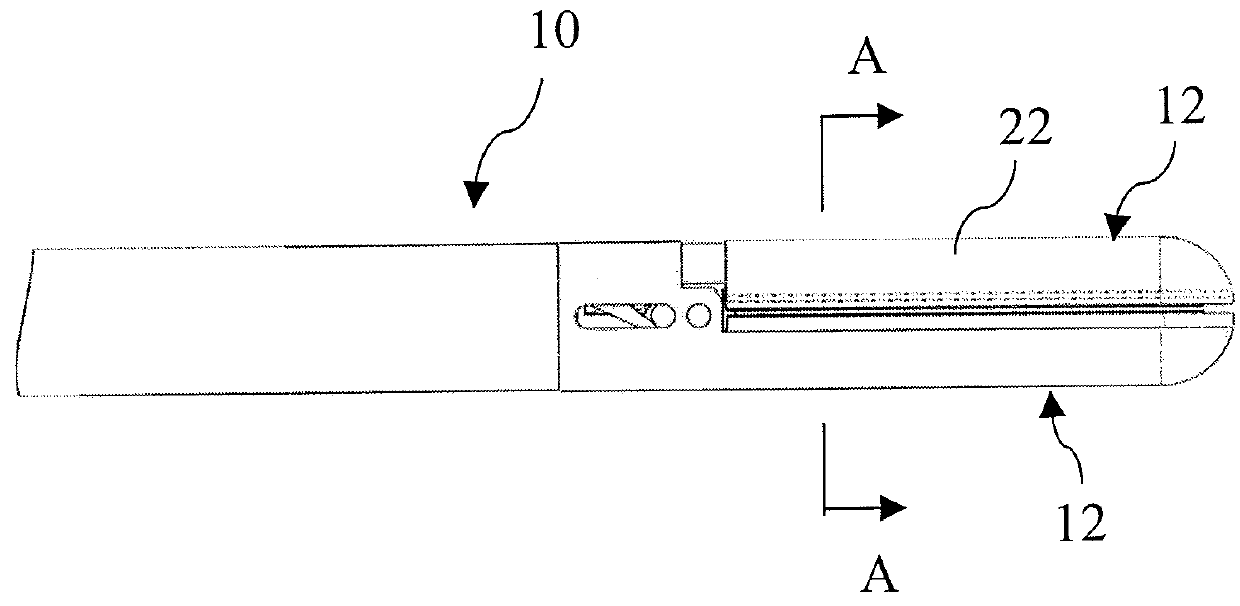
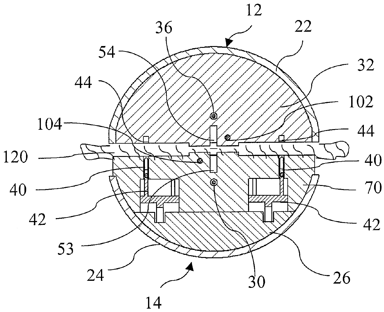
[0036]10—is a stapling apparatus end effector embodiment[0037]12—is a upper (anvil) structure[0038]14—is a lower (staples) structure[0039]16—is a cannula portion of stapling apparatus connected to a stapler handle (not shown)[0040]22—is a metal jaw body of anvil portion of the end effector[0041]24—is a metal jaw body of staple portion of the end effector[0042]26—is a support in staples portion[0043]28—staples pocket body, made from microwave absorbing material[0044]30—is a microwave antenna located in staple portion[0045]32—is an anvil staples forming portion, made from microwave absorbing material[0046]36—is a microwave antenna located in anvil portion[0047]40—staples[0048]42—is a drivers to push staples against anvil pockets[0049]42—staples drivers[0050]44—is a staple forming pockets in anvil portion of the end effector[0051]48—track for staples drivers[0052]50—cutting blade[0053]52—is a blade channel in staple portion of end effector[0054]54—is a blade channel in anvil portion of...

embodiment 100

[0079]In an alternate embodiment 100, of FIGS. 4, 6, the anvil structure 12 also includes an insert 64 made from microwave energy absorbing material and a microwave antenna 18 located inside the insert 64 which is connected with coaxial cable 112 to a microwave signal generator (not shown) to provide energy to the antenna 36. Additionally this insert 64 extends along the length of the end-effector lower jaw 12 and includes a blade channel 54 to guide the travel of a cutting blade (e.g. 50) along the channel 54 length, and within this insert 64 an optional temperature sensor 102 can be located. A metal (or other microwave reflective material) shield 62 may be disposed between the insert 64 and anvil forming plate 60.

[0080]Structurally, the various embodiments may provide the anvil portion elements are incorporated with an anvil metal body 22. Alternatively, e.g. in the embodiment of FIG. 3, the staples forming plate 32 (or 60) can be made from microwave absorbing material and microwa...


PUM


Abstract

An end effector structure (e.g. jaws structure or similar), configured with an internal antenna for delivery of electromagnetic energy in microwave range to a straight, curved or circular end effector structure in which the portion of end effector structure includes a microwave absorbing material that absorbs microwave energy emitted by the antenna and transfers microwave energy into the heat. Such end-effector also includes surgical fasteners or staples for strengthening tissue, providing a hemostasis, tissue joint and/or welding. The microwave antenna is connected by a coaxial cable with a microwave generator. The heat generated in the microwave absorbing material is applied to the treated material (e.g. tissue) by means of capturing material in the end effector (jaw structure) and heating the tissue to the desired temperature either before, during or after a stapling procedure.

Description


Claims


Application Information

Patent Timeline
Owner EXPANDOHEAT
Why Eureka
Try Eureka