
Reflection properties measuring device and manufacturing method for polarizing plates used in same

a technology of polarizing plate and measuring device, which is applied in the direction of measurement device, polarisation-affecting properties, instruments, etc., can solve the problems of inability to directly compare the print density of ink just after printing, difficulty in accurately intersecting orthogonal directions of respective polarizing directions, and change in print density due to printing, etc., to achieve accurate and easy-to-use effects

Inactive Publication Date: 2018-07-03
KONICA MINOLTA INC
View PDF17 Cites 0 Cited by
  • Summary
  • Abstract
  • Description
  • Claims
  • Application Information

AI Technical Summary

Benefits of technology

[0010]The present invention has been made in view of the above circumstances, and an object thereof is to provide a reflection property measuring device capable of, when a polarizing plate for passing illumination light therethrough and a polarizing plate for passing reflected light therethrough are arranged with respect to each other, allowing respective polarizing directions thereof to intersect orthogonally in an accurate and easy manner, and a method of manufacturing polarizing plates for use in the reflection property measuring device.
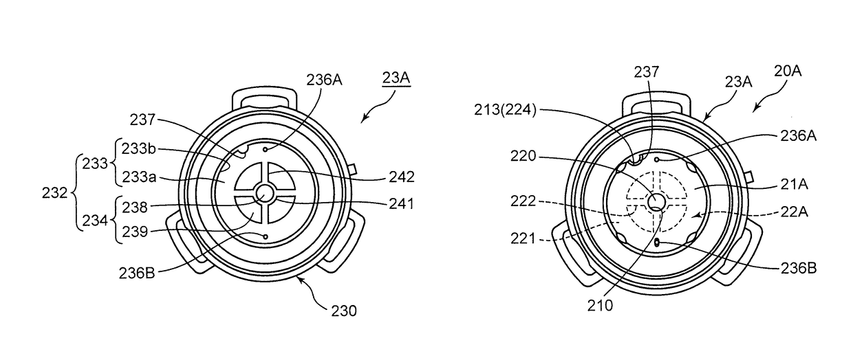
[0011]In a reflection property measuring device of the present invention, an illumination light polarizing plate inserted in an illuminating optical system for guiding illumination light to a sample surface, and a reflected light polarizing plate inserted in a light-receiving optical system for guiding reflected light as the illumination light after being reflected by the sample surface, to a light detection section, are held by a holder in a mutually superposed state in a thickness direction thereof. The holder has a fittingly-holding portion for setting a held posture, and each of the illumination light polarizing plate and the reflected light polarizing plate has a fitting portion fittable to the fittingly-holding portion of the holder. The fitting portions are provided at positions allowing the illumination light polarizing plate and the reflected light polarizing plate to be held by the holder in respective postures where polarizing directions thereof intersect orthogonally. In a method of manufacturing polarizing plates used in the reflection property measuring device, of the present invention, the illumination light polarizing plate and the reflected light polarizing plate are manufactured by punching out the illumination light polarizing plate and the reflected light polarizing plate from the same polarizing plate material using a first die for the illumination light polarizing plate and a second die for the reflected light polarizing plate. Therefore, the reflection property measuring device and the polarizing plate manufacturing method are capable of, when the illuminating polarizing plate and the reflecting polarizing plate are installed, establishing orthogonality between respective polarizing directions thereof in an accurate and easy manner.

Problems solved by technology

However, when ink in an undried state just after printing is dried, the print density changes due to dry-down.
Thus, the print density of the ink just after printing cannot be directly compared to a density of a reference sample which is in a dried state.
This causes the dry-down.
Thus, during bonding between the first polarizing plate 101 and the second polarizing plate 102, it was difficult work to allow the respective polarizing directions thereof to accurately intersect orthogonally.

Method used


Image

  • Reflection properties measuring device and manufacturing method for polarizing plates used in same
  • Reflection properties measuring device and manufacturing method for polarizing plates used in same
  • Reflection properties measuring device and manufacturing method for polarizing plates used in same

Examples


Embodiment Construction

[0024]Based on the drawings, one embodiment of the present invention will now be described. In the figures, elements or components assigned with the same reference numeral or sign mean that they are the same, and duplicated description thereof will be appropriately omitted. In this specification, a collective term will be denoted by a reference numeral or sign from which a suffix is omitted, and a term indicative of an individual element or component will be denoted by a reference numeral or sign with a suffix.

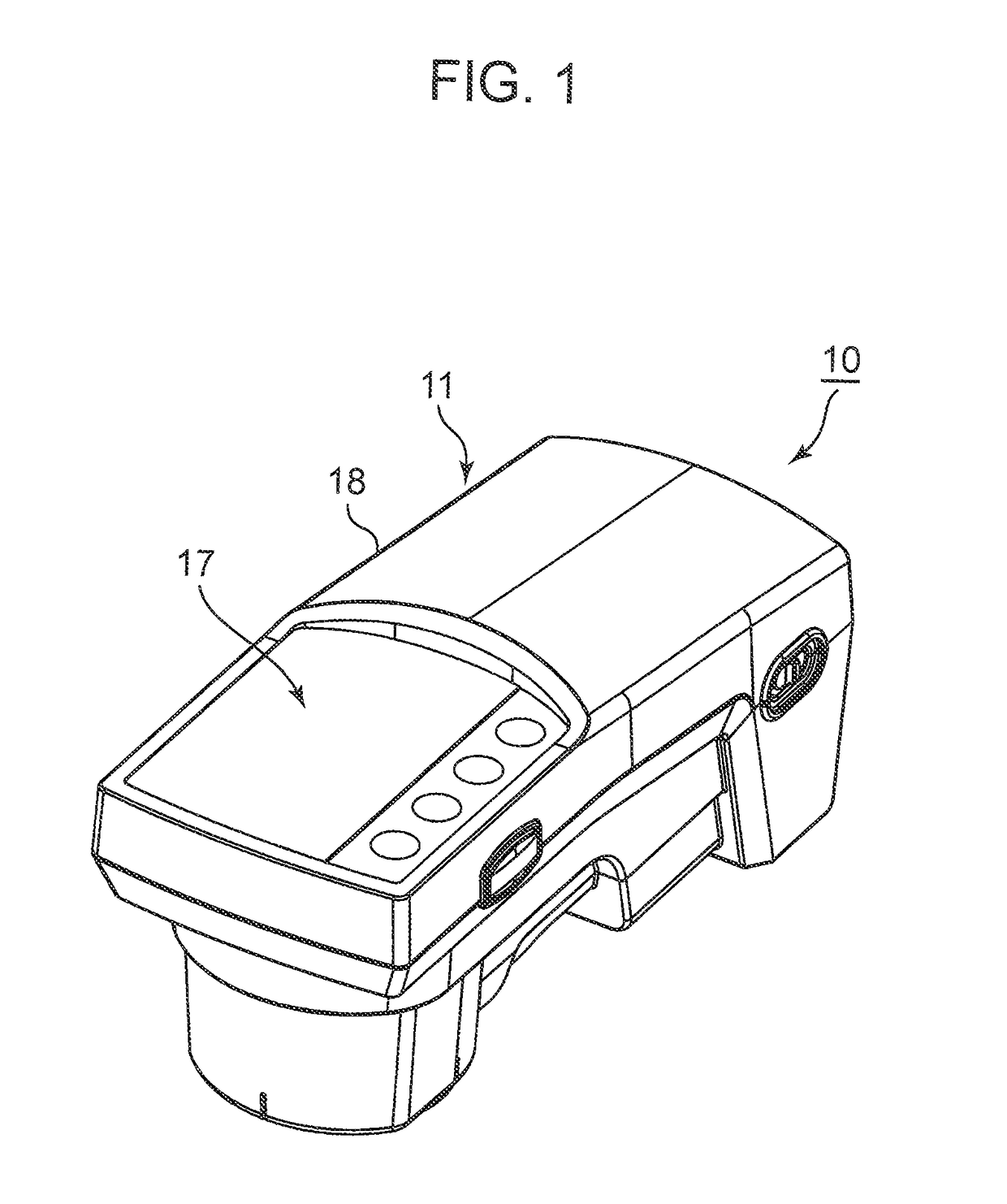
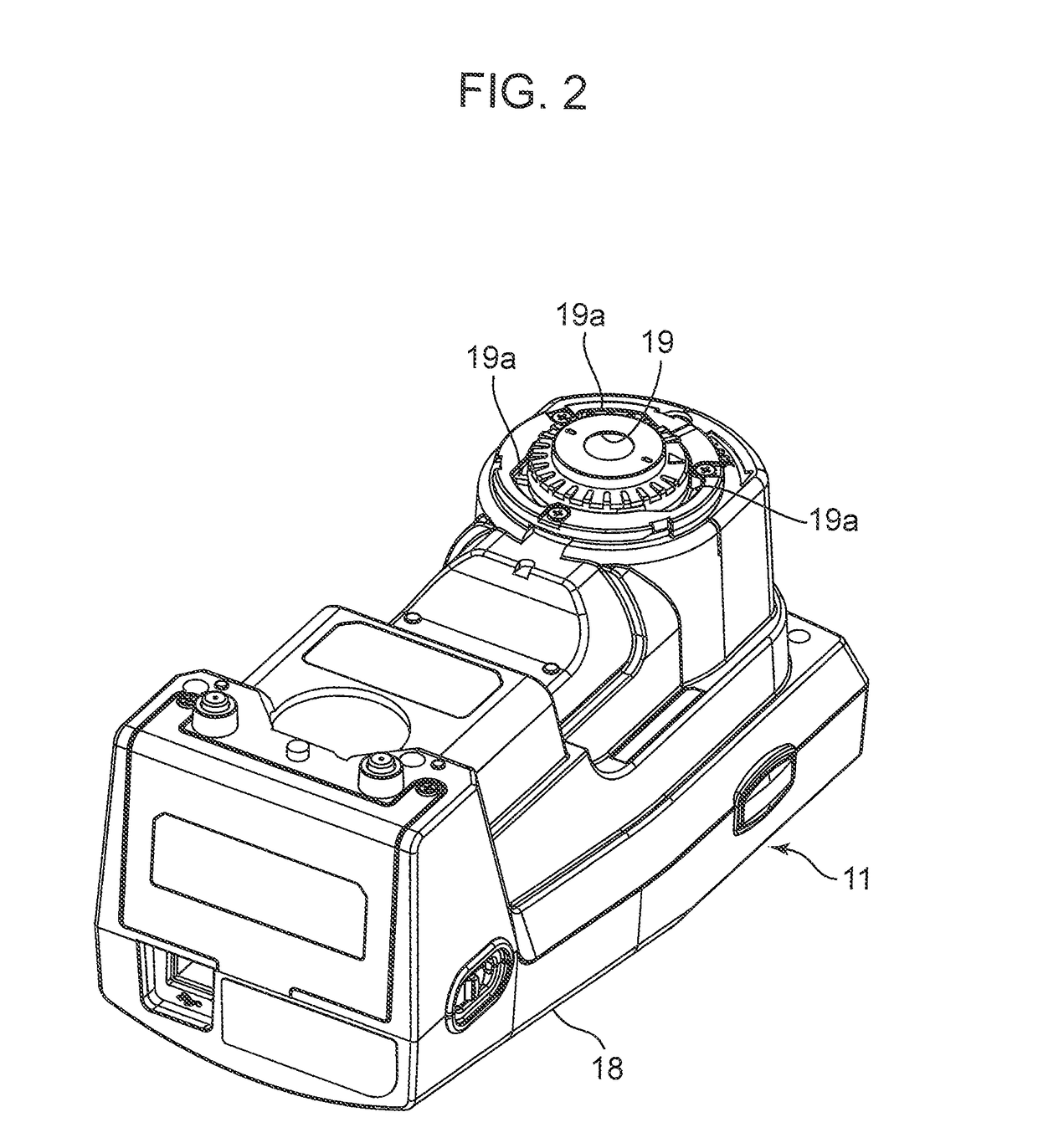
[0025]FIG. 1 is a perspective view of a color densitometer according to this embodiment, when viewed from an upper side thereof. FIG. 2 is a perspective view of the color densitometer, when viewed from a lower side thereof, wherein a polarization filter unit is detached therefrom. FIG. 3 is a block diagram illustrating a structure of the color densitometer. FIG. 4 is an enlarged explanatory diagram of optical paths of illumination light and reflected light in the vicinity of a...


PUM

PropertyMeasurementUnit
angleaaaaaaaaaa
angleaaaaaaaaaa
rotation angleaaaaaaaaaa

Abstract

A reflection property measuring device comprising illumination light and reflected light polarizing plates held by a holder in a mutually superposed state in a thickness direction thereof, wherein the holder has a fittingly-holding portion for setting a held posture, and each of the polarizing plates has a fitting portion fittable to the fittingly-holding portion. The fitting portions of the polarizing plates are provided at positions allowing the polarizing plates to be held by the holder in respective postures where polarizing directions thereof intersect orthogonally. A manufacturing method is disclosed for polarizing plates used in the device, wherein the illumination light and reflected light polarizing plates are manufactured in such a manner as to be punched out from the same polarizing plate material.

Description

RELATED APPLICATIONS[0001]This is a U.S. National Phase Application under 35 USC 371 of International Application No. PCT / JP2013 / 006781 filed on Nov. 19, 2013.TECHNICAL FIELD[0002]The present invention relates to a reflection property measuring device for measuring a reflection property of a sample surface, for example, for color evaluation of a printed matter, and a method of manufacturing polarizing plates for use in the reflection property measuring device.BACKGROUND ART[0003]Control of print quality in a printed matter (e.g., ink color adjustment) is performed by measuring a reflection property such as a print density or color values of ink on a CMYK (Cyan, Magenta, Yellow, Black) test patch. For example, a print density of ink is measured according to ISO 5-4. In this measurement, a so-called 45 / 0 geometry in which illumination light is emitted in a direction at 45° with respect to a normal line to a sample surface (in a 45-degree direction), and, among reflected light rays ref...

Claims


Application Information

Patent Timeline
Patent Type & Authority Patents(United States)
IPC IPC(8): G01N21/21G01N21/25G01N33/32
CPCG01N21/21G01N21/251G01N2201/063G01N33/32
Inventor NAGASHIMA, YOSHIYUKITSURUTANI, KATSUTOSHI
Owner KONICA MINOLTA INC
Learn More