
Assembled battery circuit, capacitance coefficient detection method, and capacitance coefficient detection program

a battery circuit and capacitance coefficient technology, applied in secondary cell servicing/maintenance, instruments, electrochemical generators, etc., can solve the problems of inability to determine the state of deterioration, method accuracy is limited, and it is not easy to detect soc in the potential plateau region. achieve the effect of easy and accurate manner

Active Publication Date: 2020-11-24
MURATA MFG CO LTD
View PDF20 Cites 1 Cited by
  • Summary
  • Abstract
  • Description
  • Claims
  • Application Information

AI Technical Summary

Benefits of technology

[0010]Accordingly, a main object of the present disclosure is to provide an assembled battery circuit that is configured to detect a capacitance coefficient even in the potential plateau region in an easy and accurate manner.
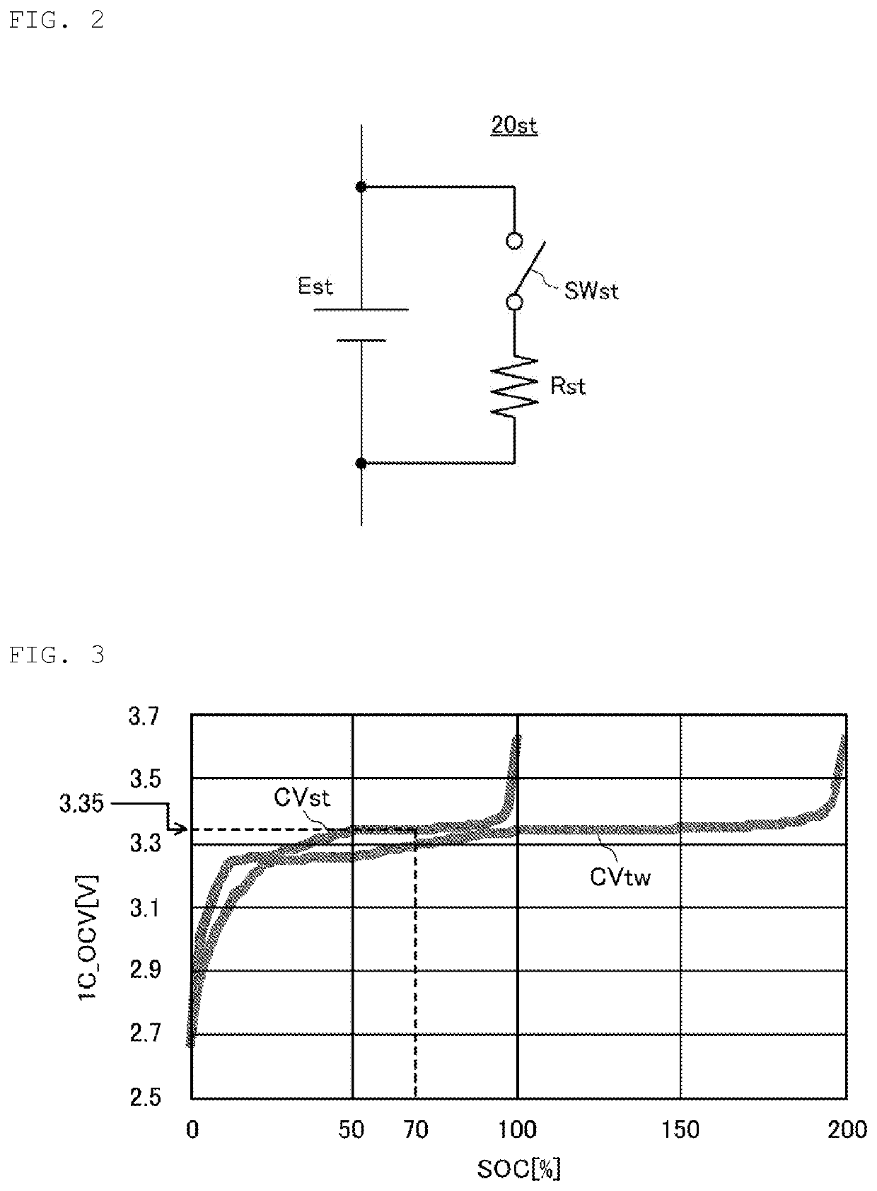
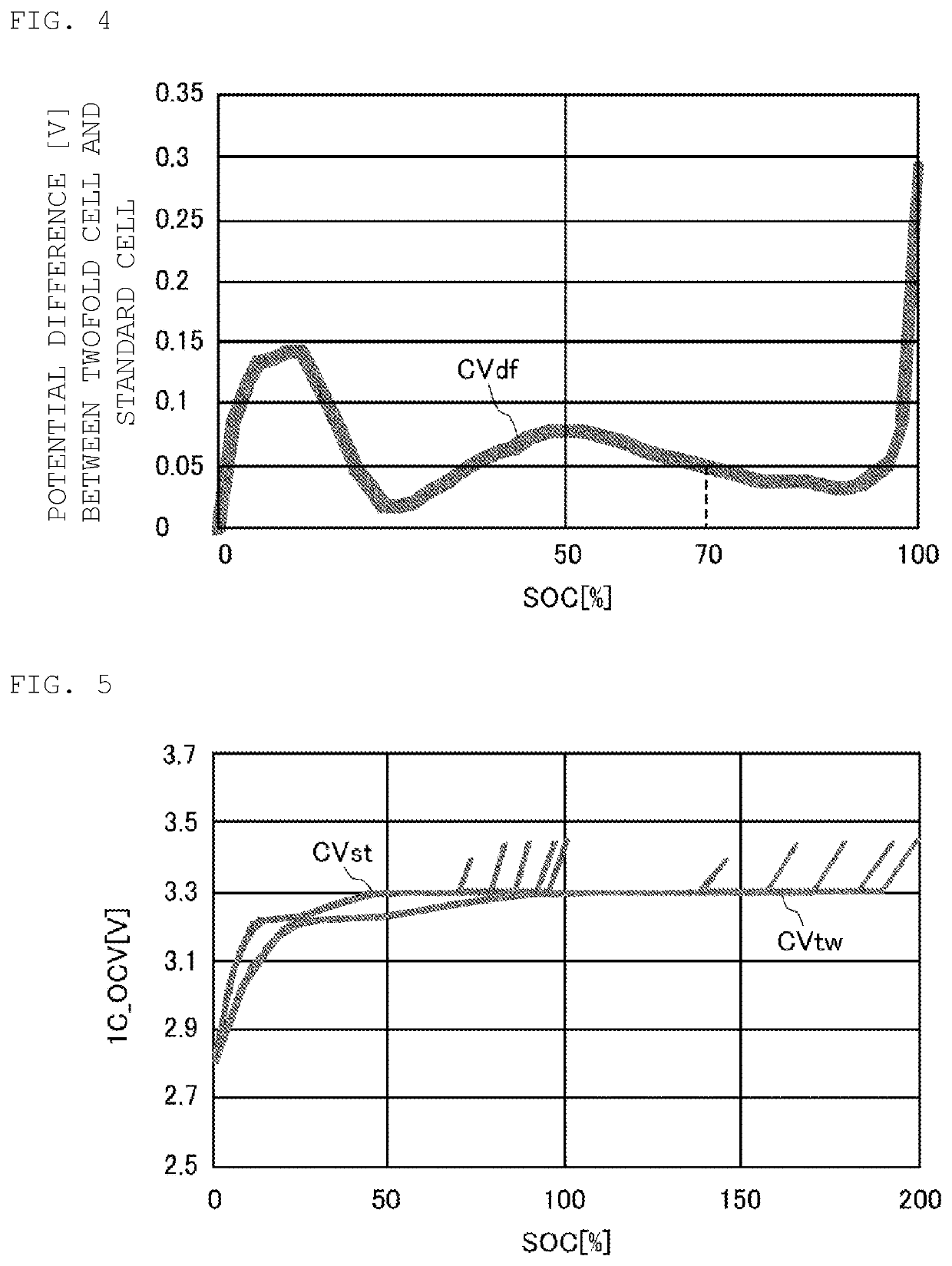
[0012]According to the exemplary embodiment, the standard cell has the standard capacitance (i.e., one or more first capacitances) and the specific cell has the capacitance exceeding the standard capacitance (the capacitance of the specific cell can be considered a second capacitance). Accordingly, the potential difference may fluctuate significantly on the potential difference-capacitance coefficient characteristic curve even in the capacitance coefficient region (i.e., the potential plateau region) with less fluctuation in the voltage of the standard cell. Using this potential difference-capacitance coefficient characteristic curve enables the detection of the capacitance coefficient of the standard cell even in the potential plateau region in an easy and accurate manner.
[0014]Referring to the standard cell voltage-capacitance coefficient characteristic curve and / or the specific cell voltage-capacitance coefficient characteristic curve enables the risk of wrong detection of the capacitance coefficient value of the standard cell to be reduced.
[0017]Referring to the potential difference-capacitance coefficient characteristic curve enables a charging balance to be adjusted between the standard cells even in the potential plateau region.
[0018]Preferably, the specific cell is connected in series to the standard cell such that the voltage of the specific cell and the voltage of the standard cell coincide with each other in a position where the values of the standard cell capacitance coefficient and the specific cell capacitance coefficient are zero. This configuration eliminates the need for adjusting a balance between the specific cell and the standard cell.
[0021]According to the exemplary embodiments of the present disclosure, it is possible to detect the capacitance coefficient even in the potential plateau region in an easy and accurate manner.

Problems solved by technology

However, for a battery with a large potential plateau region such as a positive LFP-negative Gr battery, it is not easy to detect SOC in the potential plateau region.
This method has a limited accuracy of detection of the SOC.
However, for a positive LFP-negative Gr battery, the potential plateau region degenerates with advancement in deterioration, but Δ capacitance / ΔV remains unchanged, and it is thus not possible to determine the state of deterioration.
That is, in a battery with a large potential plateau region, SOH is quantified by integrating the current value and there is a limit on the accuracy of detection of SOH.
However, monitoring and resetting two kinds of cells different in performance and deterioration characteristics would increase complexity.
In addition, for power batteries flowing large current with low resistance, it is difficult to design two kinds of cells different in material.
Further, for a conventional winding can-type battery, there is no degree of freedom for the can and it is not easy to change the design by increasing capacitance or the like.
Therefore, the assembled battery as described in Patent Document 1 is of no practical use.

Method used


Image

  • Assembled battery circuit, capacitance coefficient detection method, and capacitance coefficient detection program
  • Assembled battery circuit, capacitance coefficient detection method, and capacitance coefficient detection program
  • Assembled battery circuit, capacitance coefficient detection method, and capacitance coefficient detection program

Examples


Embodiment Construction

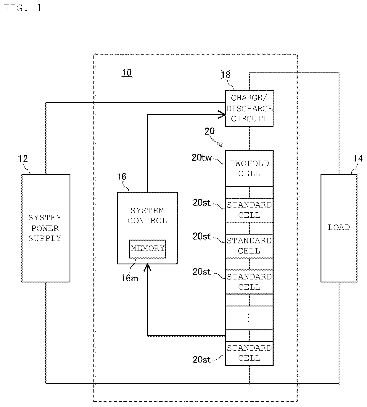
[0036]Referring to FIG. 1, an assembled battery circuit 10 according to an exemplary embodiment includes a system control circuit 16 that controls charging and discharging of an assembled battery 20 through a charge / discharge circuit 18. Moreover, the charge / discharge circuit 18 charges the assembled battery 20 with power supplied from a system power supply 12 and / or discharges power from the assembled battery 20 in response to a load 14 under control of the system control circuit 16.

[0037]In an exemplary aspect, the assembled battery 20 is formed by connecting in series Kmax standard cells 20st and a single twofold cell (specific cell) 20tw. The plurality of standard cells 20st and the twofold cell 20tw are formed by stacking positive electrodes and negative electrodes with separators interposed therebetween, storing in a laminate, charging with an electrolyte solution, and then sealing. The constant Kmax is an integer of 2 or larger, for example, “7” in an aspect. The standard cel...


PUM

PropertyMeasurementUnit
open-circuit voltageaaaaaaaaaa
capacitanceaaaaaaaaaa

Abstract

An assembled battery is formed from multiple standard cells each having a standard capacitance and a single twofold cell having a capacitance twofold larger than the standard capacitance. When detecting the SOC of a reference standard cell, a system control circuit acquires from a memory a potential difference-SOC characteristic curve indicating the relationship between the potential difference between the reference standard cell and the twofold cell and the SOC of the reference standard cell. Moreover, the system control circuit detects the potential difference between the reference standard cell and the twofold cell, and then compares the detected potential difference with the potential difference-SOC characteristic curve to detect the SOC value of the reference standard cell.

Description

CROSS REFERENCE TO RELATED APPLICATIONS[0001]The present application is a continuation of PCT / JP2017 / 021382 filed Jun. 8, 2017, which claims priority to Japanese Patent Application No. 2016-123247, filed Jun. 22, 2016, the entire contents of each of which are incorporated herein by referenceTECHNICAL FIELD[0002]The present disclosure relates to an assembled battery circuit, and, in particular, an assembled battery circuit that controls charge and discharge of an assembled battery formed from a standard cell with a standard capacitance and a specific cell with a capacitance exceeding the standard capacitance. The present disclosure also relates to a capacitance coefficient detection method for detecting the capacitance coefficient of the standard cell forming the assembled battery circuit and a capacitance coefficient detection program.BACKGROUND[0003]In general, to detect the state of charge (i.e., the “SOC”: the capacitance coefficient of the battery, specifically, the depth of cha...

Claims


Application Information

Patent Timeline
Patent Type & Authority Patents(United States)
IPC IPC(8): G01R31/389H01M10/44G01R31/36H02J7/00H01M10/48H01M10/42
CPCG01R31/36H01M10/44H01M10/48G01R31/389H01M10/482H01M10/441H02J7/0047G01R31/3648H01M2010/4271G01R31/3835G01R31/392G01R31/378Y02E60/10
Inventor SANO, KOSUKE
Owner MURATA MFG CO LTD
Learn More