Method of manufacturing a sub-muffler outer cylinder

a manufacturing method and technology of a sub-muffler are applied in the field of manufacturing methods of sub-muffler outer cylinders, which can solve the problems of increasing equipment costs and achieve the effect of low-cost equipmen

Active Publication Date: 2018-07-10
TOYOTA JIDOSHA KK
View PDF12 Cites 0 Cited by
  • Summary
  • Abstract
  • Description
  • Claims
  • Application Information

AI Technical Summary

Benefits of technology

[0008]The present invention has been made in view of the aforementioned circumstances and aims to provide a manufacturing method and a manufacturing device of a sub-muffler outer cylinder capable of manufacturing a cylindrical-shaped body having a polygonal cross-sectional shape even with low-cost equipment.
[0010]According to such a configuration, it is possible to manufacture a sub-muffler outer cylinder having a polygonal cross-sectional shape even with low-cost equipment.
[0014]According to such a configuration, it is possible to manufacture a sub-muffler outer cylinder having a polygonal cross-sectional shape with low-cost equipment.
[0015]According to the present invention, it is possible to provide a manufacturing method and a manufacturing device of a sub-muffler outer cylinder capable of forming a cylindrical-shaped body having a polygonal cross-sectional shape even with low-cost equipment.

Problems solved by technology

This method requires, however, a plurality of dedicated press dies depending on the cross-sectional shape of the sub-muffler outer cylinder, which increases the equipment cost.

Method used


Image

  • Method of manufacturing a sub-muffler outer cylinder
  • Method of manufacturing a sub-muffler outer cylinder
  • Method of manufacturing a sub-muffler outer cylinder

Examples


first embodiment

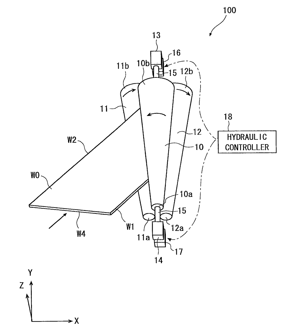
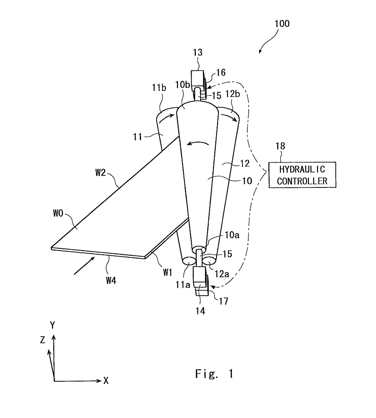
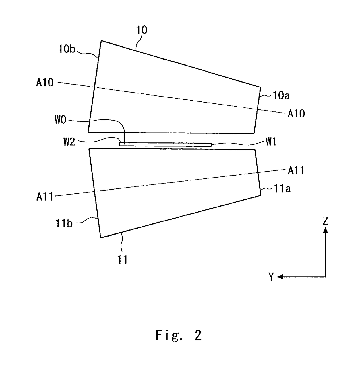
[0028]With reference to FIGS. 1 to 15, a manufacturing method according to a first embodiment will be described. FIGS. 1 to 8 are schematic views showing processes of the manufacturing method according to the first embodiment. FIG. 9 is a curvature with respect to a push-in amount by a roll. FIG. 10 is a perspective view of a cylindrical-shaped body. FIG. 11 is an expansion view of the cylindrical-shaped body. FIGS. 12 and 13 are schematic views for describing a relation among a dimension of a formed product, a radius of a roll, and the push-in amount by the roll. FIG. 14 is a perspective view of a sub-muffler. FIG. 15 is a schematic view showing the sub-muffler arranged at the underside of a vehicle. In FIGS. 2-5, 7, and 8, for the sake of clarity of the drawings, bearing housings 13 and 14 (described later) and hydraulic cylinders 16 and 17 (described later) are not shown.

[0029]First, a manufacturing device used in the manufacturing method according to the first embodiment will be...

second embodiment

[0046]With reference to FIGS. 16-19, a manufacturing method according to a second embodiment will be described. FIGS. 16 and 17 are schematic views showing processes of the manufacturing method according to the second embodiment. FIG. 18 is a perspective view of a cylindrical-shaped body. FIG. 19 is a perspective view of a sub-muffler. In FIG. 17, the bearing housings 13 and 14 and the hydraulic cylinders 16 and 17 are not shown for the sake of clarity of the drawing.

[0047]First, a manufacturing device used in the manufacturing method according to the second embodiment will be described. The manufacturing device used in the manufacturing method according to the second embodiment includes the same configurations as those of the roll bending device 100 except for the configurations of the push roll and the receive rolls. Elements of this embodiment which are the same as those of the first embodiment are denoted by the same reference symbols as those of the first embodiment and the des...


PUM

PropertyMeasurementUnit
taper angleaaaaaaaaaa
resistanceaaaaaaaaaa
shapeaaaaaaaaaa

Abstract

A manufacturing method of a sub-muffler outer cylinder is provided. The manufacturing method includes pushing one push roll toward two receive rolls, and then bending a plate-shape workpiece to form the sub-muffler outer cylinder made of a cylindrical-shaped body. A push-in amount in a part of the workpiece corresponding to a corner part of the cylindrical-shaped body is made larger than a push-in amount in a part of the workpiece corresponding to a side part of the cylindrical-shaped body to form the cylindrical-shaped body having a polygonal cross-sectional shape.

Description

INCORPORATION BY REFERENCE[0001]This application is based upon and claims the benefit of priority from Japanese patent application No. 2014-112297, filed on May 30, 2014, the disclosure of which is incorporated herein in its entirety by reference.BACKGROUND OF THE INVENTION[0002]1. Field of the Invention[0003]The present invention relates to a manufacturing method and a manufacturing device of a sub-muffler outer cylinder, and more particularly, to a manufacturing method and a manufacturing device of a sub-muffler outer cylinder to form a cylindrical-shaped body having a polygonal cross-sectional shape.[0004]2. Description of Related Art[0005]A tapered cylindrical-shaped body may be manufactured by bending a trapezoidal plate shape workpiece or a fan plate shape workpiece. In a process of bending the workpiece, a roll bending method is used, for example.[0006]For example, Japanese Unexamined Patent Application Publication No. 2012-236207 discloses a roll bending method using three t...

Claims


Application Information

Patent Timeline
Patent Type & Authority Patents(United States)
IPC IPC(8): B21D5/14B21D53/88B21C37/18F01N13/18
CPCB21D5/14B21C37/185B21D53/88F01N13/1894F01N13/1872Y10T29/49398Y10T29/494
Inventor HOMMA, HIDEKIYAMAMOTO, AKIYOSHI
Owner TOYOTA JIDOSHA KK
Why Eureka
Try Eureka