Deburring tool

a technology of deburring tools and tools, which is applied in the field of deburring tools, can solve the problems of preventing the parts from working, frequent replacement, and increasing wear on the parts involved, so as to reduce or eliminate the need for cumbersome tools and equipment, reduce the time spent deburring, and increase the efficiency in the field.

Inactive Publication Date: 2018-07-10
GDE
View PDF29 Cites 5 Cited by
  • Summary
  • Abstract
  • Description
  • Claims
  • Application Information

AI Technical Summary

Benefits of technology

[0008]A deburring tool is designed to be used in a handheld power drill and reduces or eliminates the need for cumbersome tools and equipment. The deburring tool can reduce the time spent deburring and increase efficiency in the work place and in the field.
[0011]In some embodiments, the proportions of the cone body, the cone tool face, the flutes, the flute cutting edge, the internal chamfer, the external chamfer, the radius, the relief portion of the flute, the cone base, the tool shaft portion, the shaft grip surface and the relief cut for tool engagement are engineered to make the tool convenient to use with a handheld drill.

Problems solved by technology

In many cases, it is necessary or preferred to remove these burrs, a process known as deburring, as the presence of burrs can lead to increased wear on the parts involved, leading to frequent replacement, or even preventing the parts from working as intended.
Burrs formed in drilled holes can cause fastener and material problems.
Burrs can lead to concentrated stress at the edges of holes, thereby decreasing the material's resistance to fracture.
Burrs also increase the friction and heat between moving parts.
In addition, burrs can interfere with the proper placement of fasteners, and can also lead to corrosion.
Furthermore, the sharp edges of many burrs tend to concentrate electric charge and can lead to spontaneous electronic discharge.
Manual deburring is often time and labor intensive.
In many instances, deburring accounts for a large amount of manufacturing costs.
Unfortunately these processes are either expensive, messy, and / or require large equipment.

Method used


Image

  • Deburring tool
  • Deburring tool
  • Deburring tool

Examples


Embodiment Construction

)

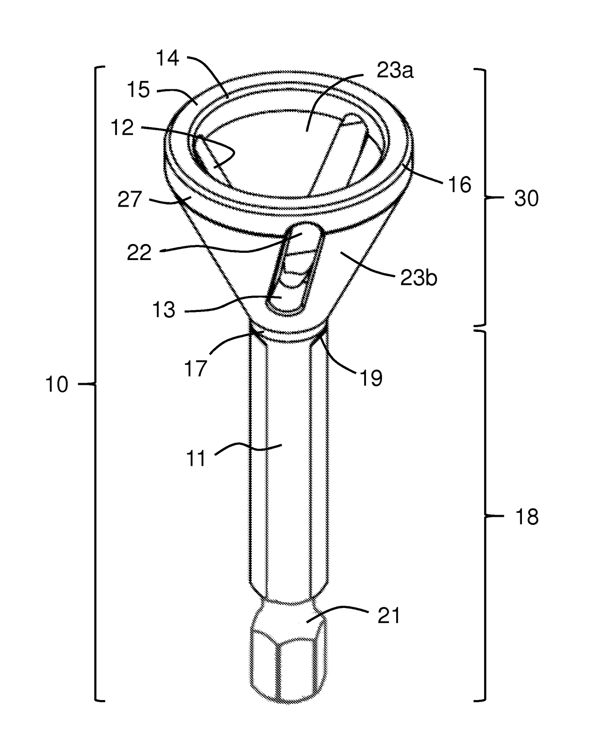
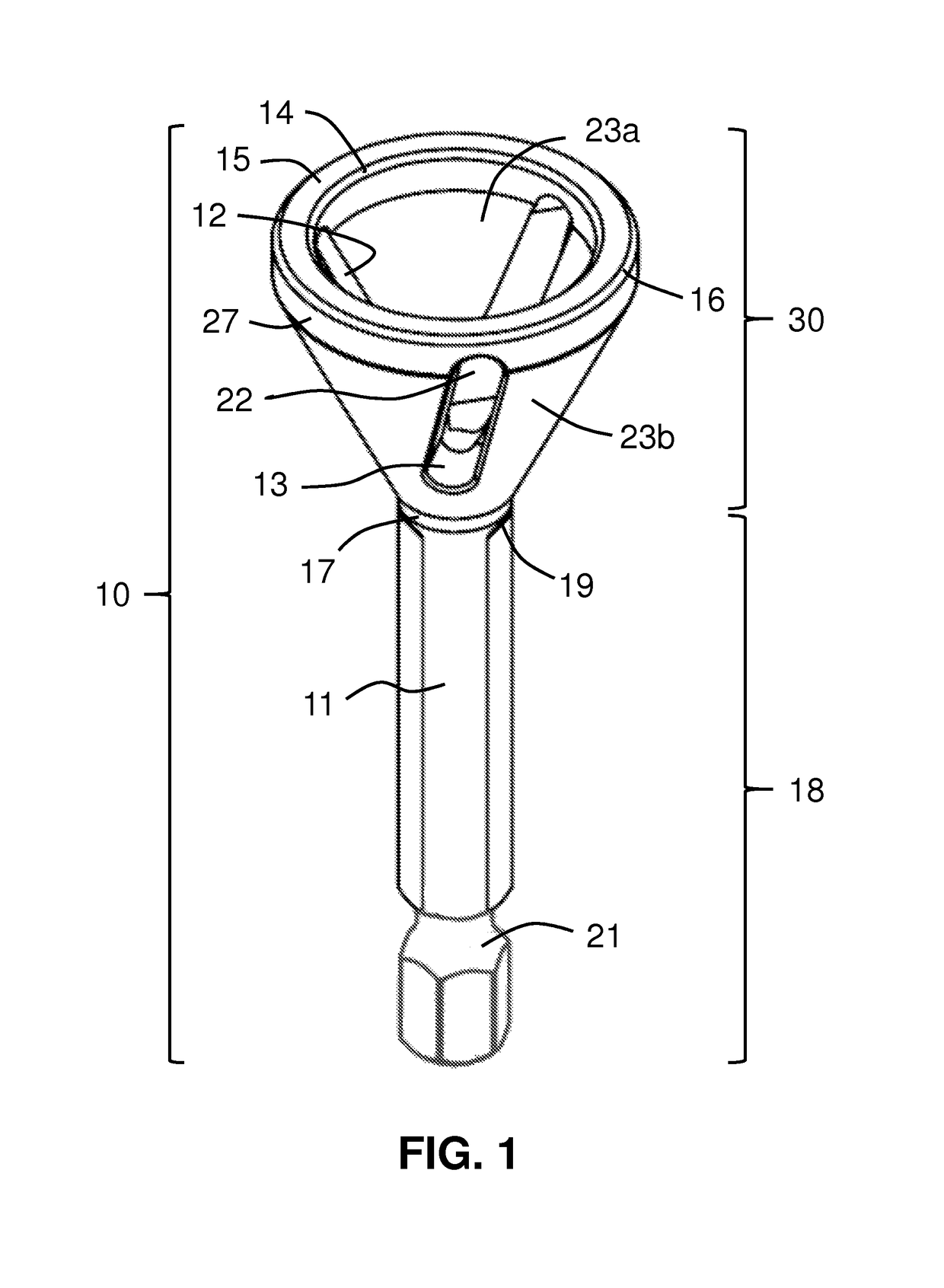
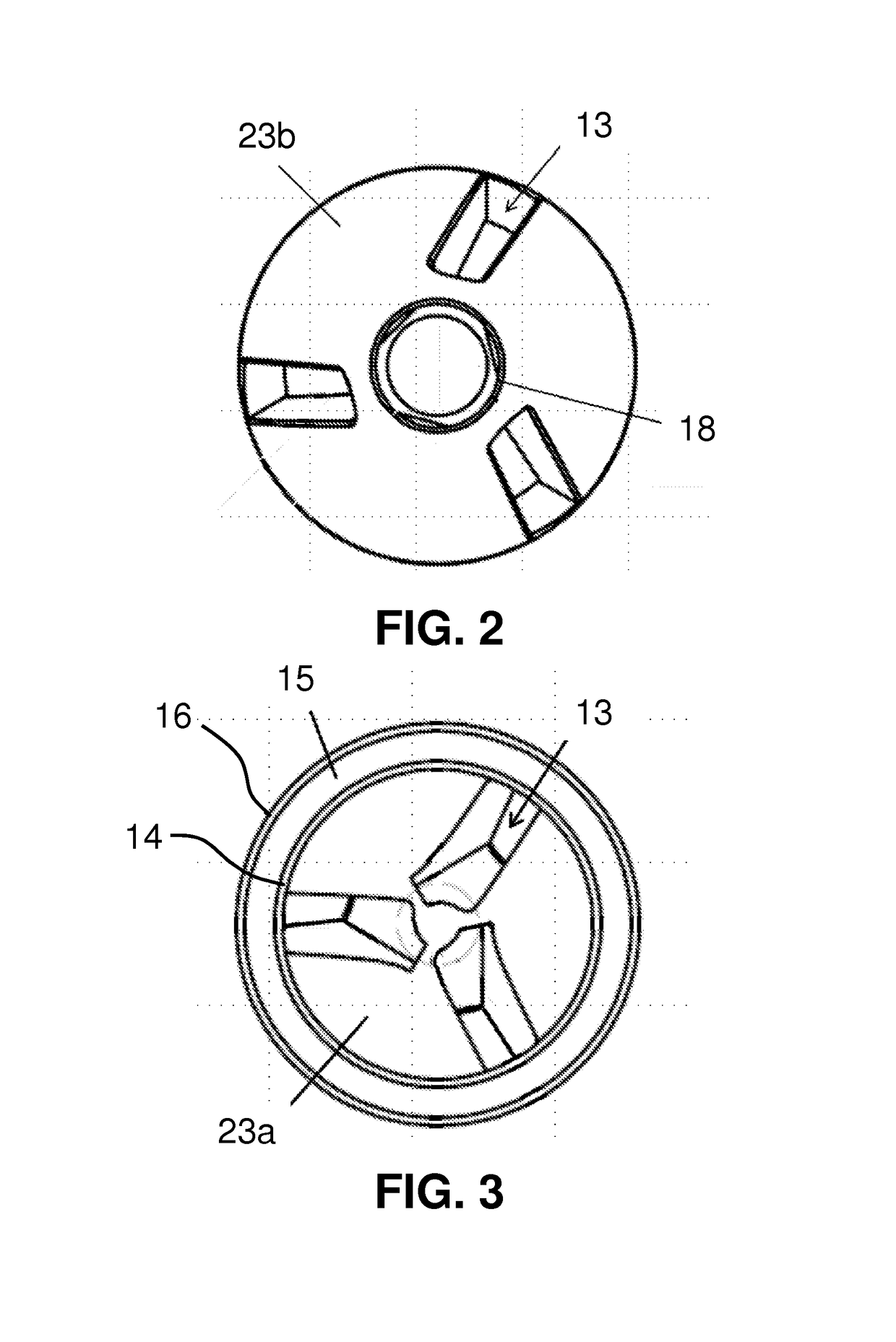
[0024]FIG. 1 shows a perspective view of deburring tool 10. Deburring tool 10 has tool shaft portion 18 and conical top portion 30.

[0025]Conical top portion 30 is made up of internal cone surface 23a and external cone surface 23b which are capped by tool face 15. Tool face 15 is connected to internal cone body 23a and external cone body 23b via internal chamfer 14 and external chamfer 16, respectively. A collar portion 27 interconnects external chamfer 16 and external cone body 23b.

[0026]Conical top portion 30 has formed therein at least one flute 13 having at least one cutting edge 12. Conical top portion 30 also has at least one relief portion 22 associated with flute 13. In the particular embodiment shown, conical top portion 30 has three flutes 13. However, other embodiments can employ various numbers of flutes 13 with corresponding cutting edges 12 and relief portions 22, depending upon the nature of the bar stock to be deburred.

[0027]Conical top portion 30 attaches to tool s...


PUM

PropertyMeasurementUnit
angleaaaaaaaaaa
angleaaaaaaaaaa
distanceaaaaaaaaaa

Abstract

A deburring tool has a hollow top portion having an interior conical surface and an exterior surface. The exterior surface of the deburring tool is preferably conical. The top portion has a plurality of flutes formed therein and extending between the interior and exterior surfaces. Each of the flutes has a cutting edge formed at the interior conical surface. In operation, rotation of the deburring tool about a longitudinal axis removes burrs projecting from bar stock contacting the interior conical surface. A method of deburring bar stock comprises: (a) rotating the deburring tool about a longitudinal axis, and (b) contacting the bar stock to the deburring tool interior conical surface.

Description

CROSS-REFERENCE TO RELATED APPLICATIONS[0001]This application is a continuation of International Application No. PCT / US2014 / 040096 having a filing date of May 29, 2014, entitled “Deburring Tool”, which claimed priority benefits from U.S. provisional patent application Ser. No. 61 / 956,039 filed on May 31, 2013, also entitled “Deburring Tool”. The '096 international application and the '039 provisional application are each hereby incorporated by reference herein in its entirety.FIELD OF THE INVENTION[0002]The present invention relates to deburring tools. In particular, the present invention relates to a tool that can be attached to a handheld drill and used to deburr bar stock.BACKGROUND OF THE INVENTION[0003]Burrs, raised or frayed edges of material often result from machining operations such as grinding, drilling, milling, engraving, and turning. In many cases, it is necessary or preferred to remove these burrs, a process known as deburring, as the presence of burrs can lead to incr...

Claims


Application Information

Patent Timeline
Patent Type & Authority Patents(United States)
IPC IPC(8): B23B51/10B23B5/16
CPCB23B5/167B23B51/103Y10T408/899B23B2222/84Y10T408/89B23B2220/08
Inventor FERGUSON, DANIEL EARL
Owner GDE
Why Eureka
Try Eureka