
Cowl cross member for vehicle

a cross member and vehicle technology, applied in the direction of vehicular safety arrangments, pedestrian/occupant safety arrangements, transportation and packaging, etc., can solve the problems of increasing the likelihood of an airbag accident in the inability to ensure the deployment direction of an airbag, so as to reduce the injury to the upper body of a passenger, improve the surface rigidity, and reduce the impact of the passenger

Active Publication Date: 2018-07-17
HYUNDAI MOTOR CO LTD +1
View PDF23 Cites 3 Cited by
  • Summary
  • Abstract
  • Description
  • Claims
  • Application Information

AI Technical Summary

Benefits of technology

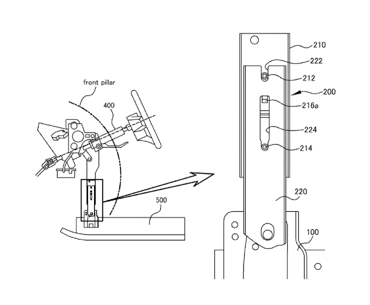
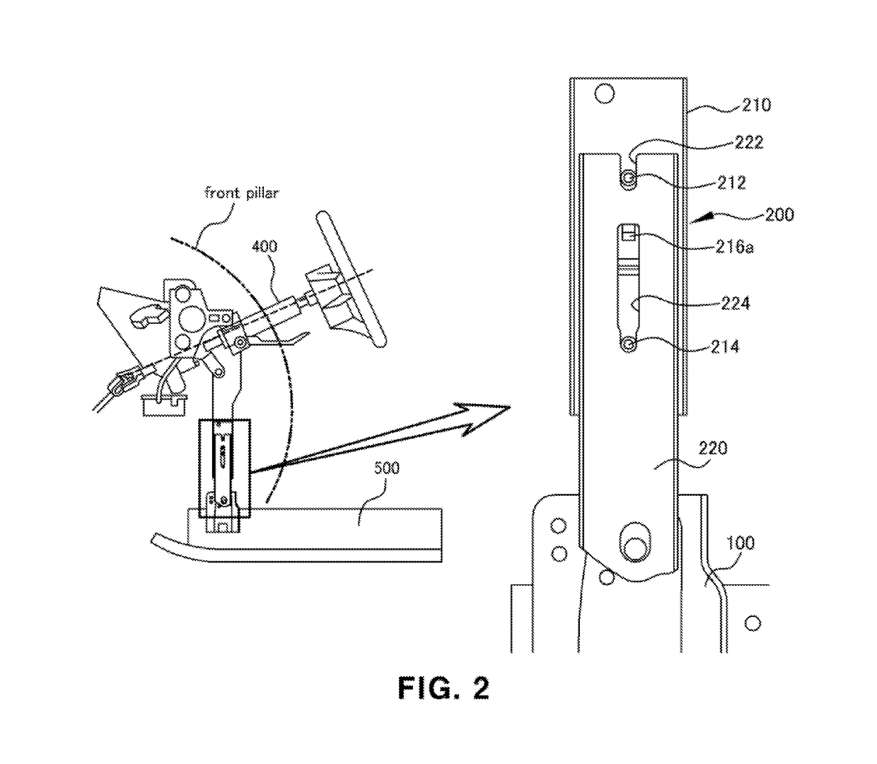
[0009]The present invention provides a cowl cross member for a vehicle, in which a center support disposed on a cowl cross bar includes multiple stages. For example, the center support may have a length that may be configured to extend via a sliding movement of the center support during a vehicle collision, and may prevent a column dive phenomenon.
[0013]In a further exemplary embodiment, the support retaining portion may include a support protrusion member that may extend to the exterior by penetrating the sliding aperture at the initial position and may intersect (e.g., capture) the center slide supporter. Further, the support protrusion member may be bent in a right angle (e.g., ‘’) shape at a first side of the support retaining portion, and a bent region may be rounded. The support retaining portion may be formed to increase surface rigidity, and may be coupled to the sliding guide.
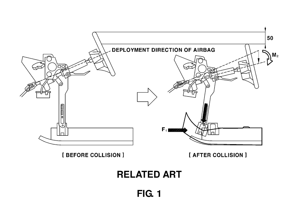
[0014]In the present invention, the center support, disposed on the cowl cross bar, may be configured to laterally translate to extend a length of the center support during a vehicle collision, and as a result, may prevent a column dive phenomenon. Due to the prevention of the column dive phenomenon, the present invention may provide a specific deployment direction of an airbag and may accordingly reduce an injury to an upper body of a passenger. As a result, stable performance regarding collision may be provided.

Problems solved by technology

Accordingly, as a result, the steering system is bent by a predetermined angle M, and a deployment direction of an airbag cannot be ensured.
The steering system causes an increase in the likelihood of an injury to an upper body of a passenger.

Method used


Image

  • Cowl cross member for vehicle
  • Cowl cross member for vehicle
  • Cowl cross member for vehicle

Examples


Embodiment Construction

[0038]Hereinafter reference will now be made in detail to various exemplary embodiments of the present invention, examples of which are illustrated in the accompanying drawings and described below. While the invention will be described in conjunction with exemplary embodiments, it will be understood that present description is not intended to limit the invention to those exemplary embodiments. On the contrary, the invention is intended to cover not only the exemplary embodiments, but also various alternatives, modifications, equivalents and other exemplary embodiments, which may be included within the spirit and scope of the invention as defined by the appended claims.

[0039]Hereinafter, the exemplary embodiment of the present invention will be described in detail with reference to the accompanying drawings. Advantages and features of the present invention and methods of achieving the advantages and features will be clear with reference to the exemplary embodiments described in detai...


PUM


Abstract

A cowl cross member for a vehicle is provided. The cowl cross member includes a cowl cross bar that has first and second ends fixed to an interior panel of a front pillar of the vehicle and is disposed in a horizontal direction at a front side of a vehicle body, with a steering column fixed thereto. A center support is vertically disposed to support a central portion of the cowl cross bar to couple the cowl cross bar at a predetermined height and is configured to adjust a length of the center support during a vehicle collision.

Description

CROSS-REFERENCE TO RELATED APPLICATION[0001]This application claims under 35 U.S.C. § 119(a) the benefit of Korean Patent Application No. 10-2015-0120767 filed on Aug. 27, 2015, the entire contents of which are incorporated herein by reference.BACKGROUND[0002](a) Technical Field[0003]The present disclosure relates to a cowl cross member for a vehicle and more particularly, to a cowl cross member for a vehicle which has a column dive prevention structure.[0004](b) Background Art[0005]Generally, a cowl cross member is installed in parallel with a vehicle body to improve strength or rigidity of the vehicle body and prevent the integrity of the vehicle body from being compromised in various directions (e.g., twisted or bent in front, rear, left and right directions). The cowl cross member couples a steering system to the vehicle body at a boundary disposed between an engine compartment of the vehicle and an interior passenger compartment of the vehicle body, and supports a duct of syste...

Claims


Application Information

Patent Timeline
Patent Type & Authority Patents(United States)
IPC IPC(8): B62D25/14B62D1/19
CPCB62D25/145B62D1/197B60R21/00
Inventor AN, JAE HYUNJANG, JUNG YOON
Owner HYUNDAI MOTOR CO LTD
Learn More