
Single-use bioreactor and head plate, and a process for manufacturing same

a single-use, bioreactor technology, applied in the direction of biomass after-treatment, transportation and packaging, rotary stirring mixers, etc., can solve the problems of inability to use in parallel bioreactor systems, disruption of subsequent processes, complex process for sterilizing and cleaning reusable bioreactors, etc., to achieve high temperature resistance

Active Publication Date: 2018-07-24
EPPENDORF SE
View PDF32 Cites 0 Cited by
  • Summary
  • Abstract
  • Description
  • Claims
  • Application Information

AI Technical Summary

Benefits of technology

The patent is about a special reactor used for growing cells that can be thrown away after use. The reactor uses a magnetic drive to rotate a mixing tool inside the reactor. This design has several benefits. First, the mixing tool is placed inside the reactor, so it doesn't have to pass through the top plate. This eliminates the risk of compromising the sterility of the reactor by not properly sealing a hole in the top plate. Additionally, the design avoids any friction that could damage the septum components. The reactor also has connectors on the outside of its head plate that have internal threads. This allows for screw connections without needing additional connector components.

Problems solved by technology

Due to limitations of space in most laboratories, minimal space requirements and in particular small footprints are striven for, not only for bioreactor systems but also for the bioreactors themselves.
Sterilizing and cleaning reusable bioreactors is a complex process.
Residues in a bioreactor which has not been fully sterilized can falsify the results of a subsequent process, or render them useless, and may cause disruption of the subsequent process.
Furthermore, the sterilization process may also expose Individual components or materials in bioreactors to stress and strain, and in some cases can damage them.
However, one disadvantage of these single-use bioreactors with flexible walls, inter alia, is that they cannot be used in parallel bioreactor systems, which are designed for dimensionally stable, reusable bioreactors.
Dimensionally stable single-use bioreactors known from the prior art are unsuitable, therefore, for use in microbiology research or in process engineering, for example.

Method used


Image

  • Single-use bioreactor and head plate, and a process for manufacturing same
  • Single-use bioreactor and head plate, and a process for manufacturing same
  • Single-use bioreactor and head plate, and a process for manufacturing same

Examples


Embodiment Construction

[0073]Some possible embodiments of the invention shall now be described by way of example with reference to the attached Figures, in which:

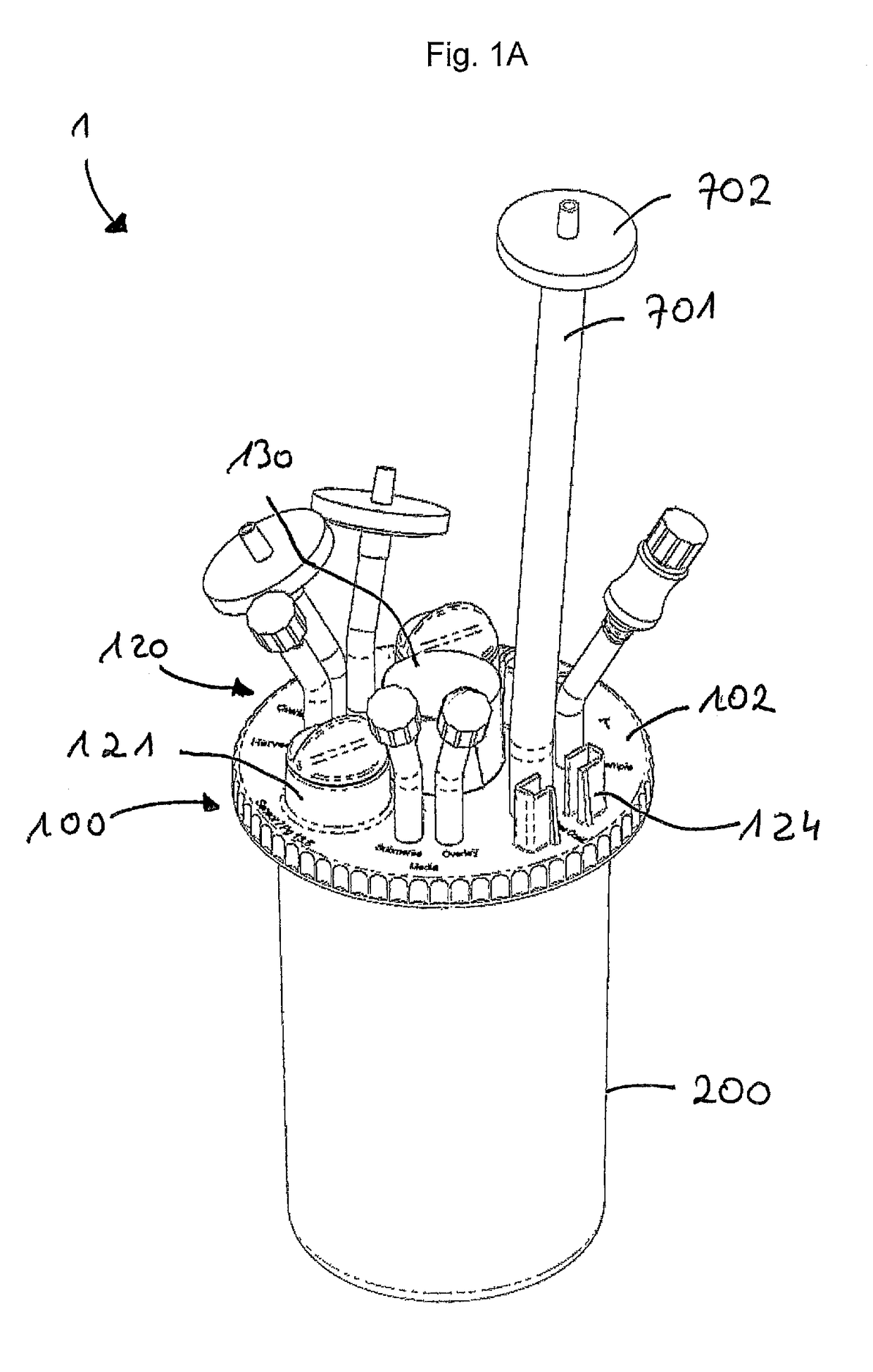
[0074]FIG. 1A: shows a three-dimensional view of an embodiment of a single-use bioreactor according to the invention;

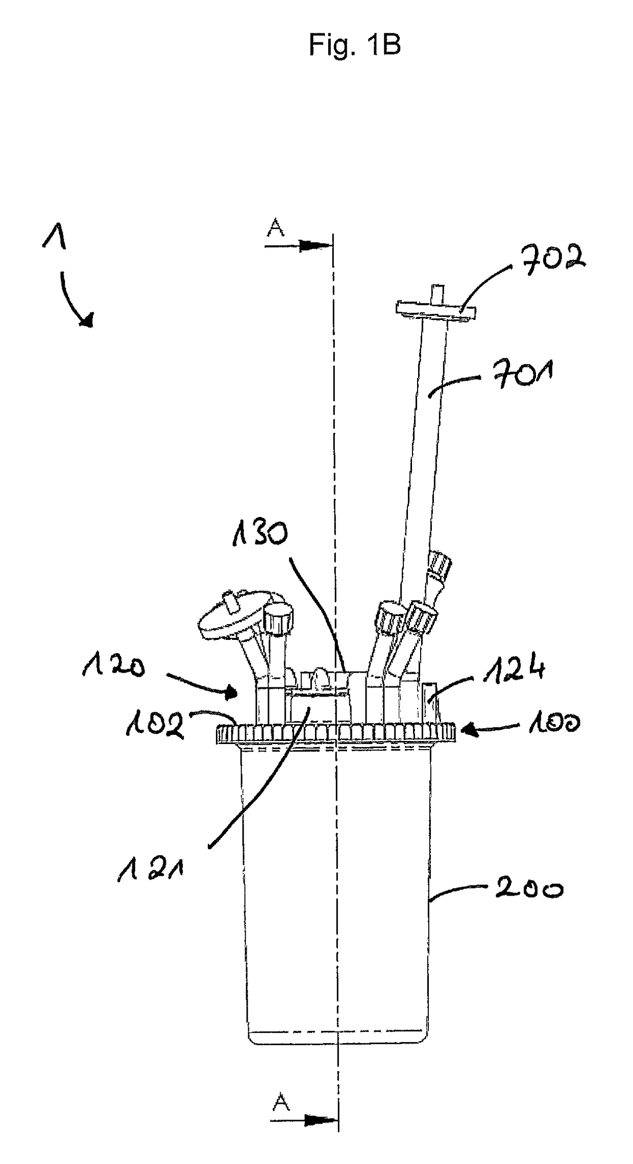
[0075]FIG. 1B: shows a side view of the single-use bioreactor in FIG. 1A;

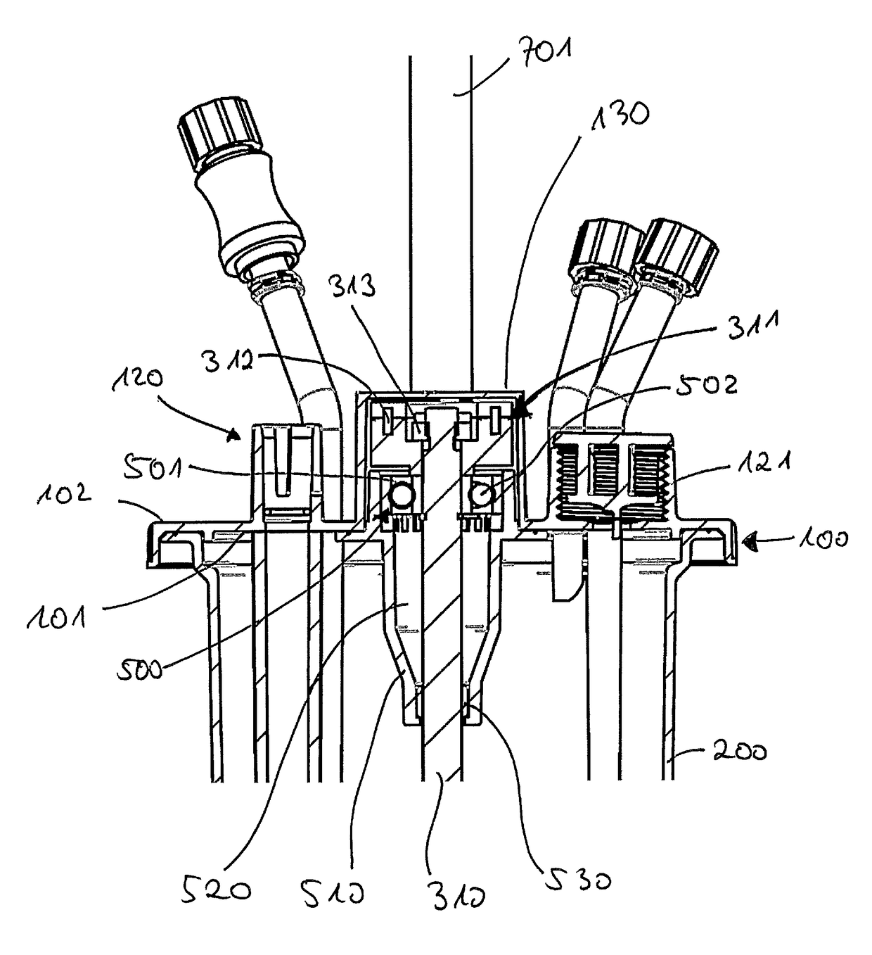
[0076]FIG. 1C: shows a cross-section of the single-use bioreactor in FIG. 1A along the sectional plane A-A in FIG. 1C;

[0077]FIG. 1D: shows an enlarged section from FIG. 1C;

[0078]FIG. 1E: an alternative embodiment of the magnetic portion;

[0079]FIG. 2A: shows a three-dimensional view of a biotechnological device comprising a single-use bioreactor, a connection device and a temperature control device;

[0080]FIG. 2B: shows a side view of the biotechnological device in FIG. 2A;

[0081]FIG. 2C: shows a plan view of the biotechnological device in FIG. 2A;

[0082]FIG. 2D: shows a cross-section of the biotechnological device in FIG. 2A along the sectional plane A-A in FIG. ...


PUM

PropertyMeasurementUnit
volumeaaaaaaaaaa
volumeaaaaaaaaaa
volumeaaaaaaaaaa

Abstract

A single-use bioreactor, suitable in particular for use in a parallel bioreactor system for applications in cell culture and / or microbiology, a head plate for such a single-use bioreactor and a process for manufacturing the single-use bioreactor and the head plate. The single-use bioreactor comprises a head plate, a dimensionally stable container and a mixer, the head plate and the container enclosing a reaction chamber, and the mixer having a mixer shaft and a stirring member, said mixer shaft being mounted rotatably about a rotational axis in a bearing and the stirring member being fastened torsionally rigidly to the mixer shaft. The mixer and the bearing are arranged entirely within the reaction chamber and the mixer shaft has a magnetic portion which is arranged and adapted in such a way that it can be coupled magnetically in an axial direction to a rotary drive.

Description

[0001]This application is a National Stage Application of PCT / EP2013 / 062225, filed 13 Jun. 2013, which claims benefit of U.S. Provisional Ser. No. 61 / 660,554, filed 15 Jun. 2012, and European Application No. 12172304.3, filed 15 Jun. 2012, and the entire disclosure of these applications are incorporated herein by reference. To the extent appropriate, a claim of priority is made to each of the above disclosed applications.[0002]The invention relates to a single-use bioreactor suitable in particular for use in a preferably parallel bioreactor system for applications in cell culture and / or microbiology, comprising a head plate, a dimensionally stable container and a mixer, wherein the head plate and the container enclose a reaction chamber, the head plate having an inner side facing towards the reaction chamber, and an outer side which faces away from the reaction chamber and which has a plurality of connectors, and the mixer having a mixer shaft and a stirring member, the mixer shaft ...

Claims


Application Information

Patent Timeline
Patent Type & Authority Patents(United States)
IPC IPC(8): C12M1/00C12M1/06C12M3/00B01F27/91
CPCC12M23/28C12M23/40C12M27/02C12M23/42Y10T156/10Y10T29/49826
Inventor ARNOLD, MATTHIASKOHN, HEINZ GERHARDGULZOW, NICOEIKELMANN, SVENSELZER, SEBASTIANBEESE, JOCHENGUNTHER, CHRISTOPHERKOPOWSKI, ECKART
Owner EPPENDORF SE
Learn More