

Image forming apparatus, image forming method, and recording medium
a technology of image forming and image, applied in the direction of electrographic process apparatus, instruments, corona discharge, etc., can solve the problem of photoconductor degradation by oxid
- Summary
- Abstract
- Description
- Claims
- Application Information
AI Technical Summary
Benefits of technology
Problems solved by technology
Method used
Image



Examples
embodiment 1
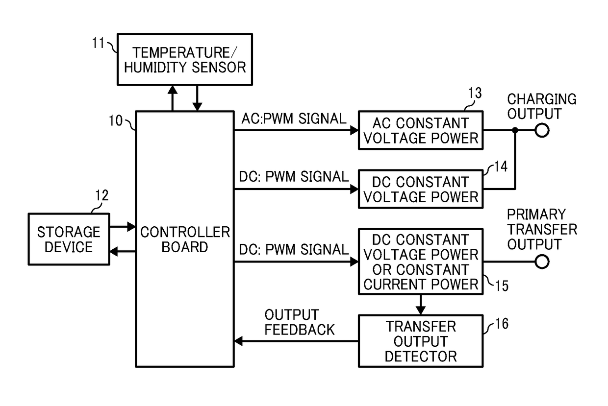
[0030]FIG. 1 is a block diagram illustrating an elemental configuration of an image forming device in an image forming apparatus for describing an electrophotography operation in this embodiment.
[0031]With reference to FIG. 1, in an electrophotography operation by an image forming device (an image formation device) 100 in an image forming apparatus 10 in this embodiment, after applying high voltage generated by a high-voltage power supply for charging 1 to a charging roller 3 and charging a photoconductor 2 as an image bearer that transfers toner to printing paper uniformly, an exposure unit 4 exposes in accordance with an image signal, and an electrostatic latent image is formed on the photoconductor 2. Subsequently, a developer (a developing device) 5 develops a toner image, and the toner image on the photoconductor 2 is transferred to an intermediate belt (an intermediate transfer belt) (also referred to as a primary transfer belt) 7 by applying high voltage generated by a high-v...
embodiment 2
[0070]In the image forming apparatus in the first embodiment, the control board 10 calculates AC voltage that the charging roller 3 as the charging unit outputs based on the detection result of the output from the intermediate belt 7 as the transfer unit detected by the transfer output detector 16. In this embodiment, furthermore, a target current value that the charging roller 3 as the charging unit outputs based on the acquired AC voltage is calculated.
[0071]In the technology described in the first embodiment, it is required to detect the minimum peak value Vac that the surface of the photoconductor 2 starts being charged at the intended potential, calculate the line between the peak value Vac and the primary transfer load impedance Z both the higher value side and the lower value side of the peak value Vac, and measure the primary transfer load impedance Z by modifying at least four peak values Vac. In addition, the control is performed each time the environment changes or the ch...
PUM
 Abstract
Description
Claims
Application Information