Methods to shorten calibration times for powered devices

a powered device and calibration time technology, applied in the field of surgical staplers, can solve the problems of time-consuming calibration and difficulty in precise calibration

Active Publication Date: 2018-08-07
COVIDIEN LP
View PDF433 Cites 992 Cited by
  • Summary
  • Abstract
  • Description
  • Claims
  • Application Information

AI Technical Summary

Problems solved by technology

This calibration can be time consuming, requiring full strokes of the translating components to their full proximal and distal stop positions.
Additionally, precise calibration may be difficult where tolerances between mating components and / or gear meshes have some gap or slip associated to enable assembly of the motor-powered surgical stapler.

Method used


Image

  • Methods to shorten calibration times for powered devices
  • Methods to shorten calibration times for powered devices
  • Methods to shorten calibration times for powered devices

Examples


Embodiment Construction

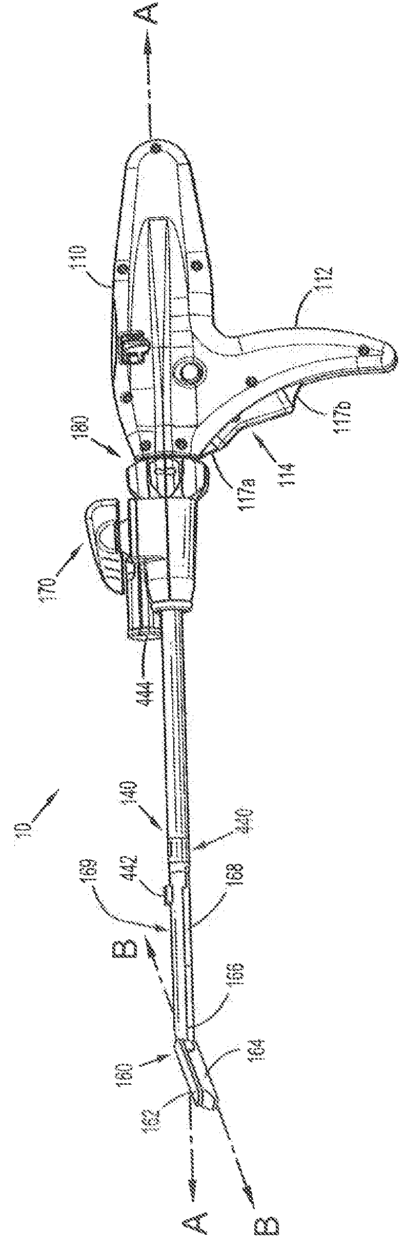
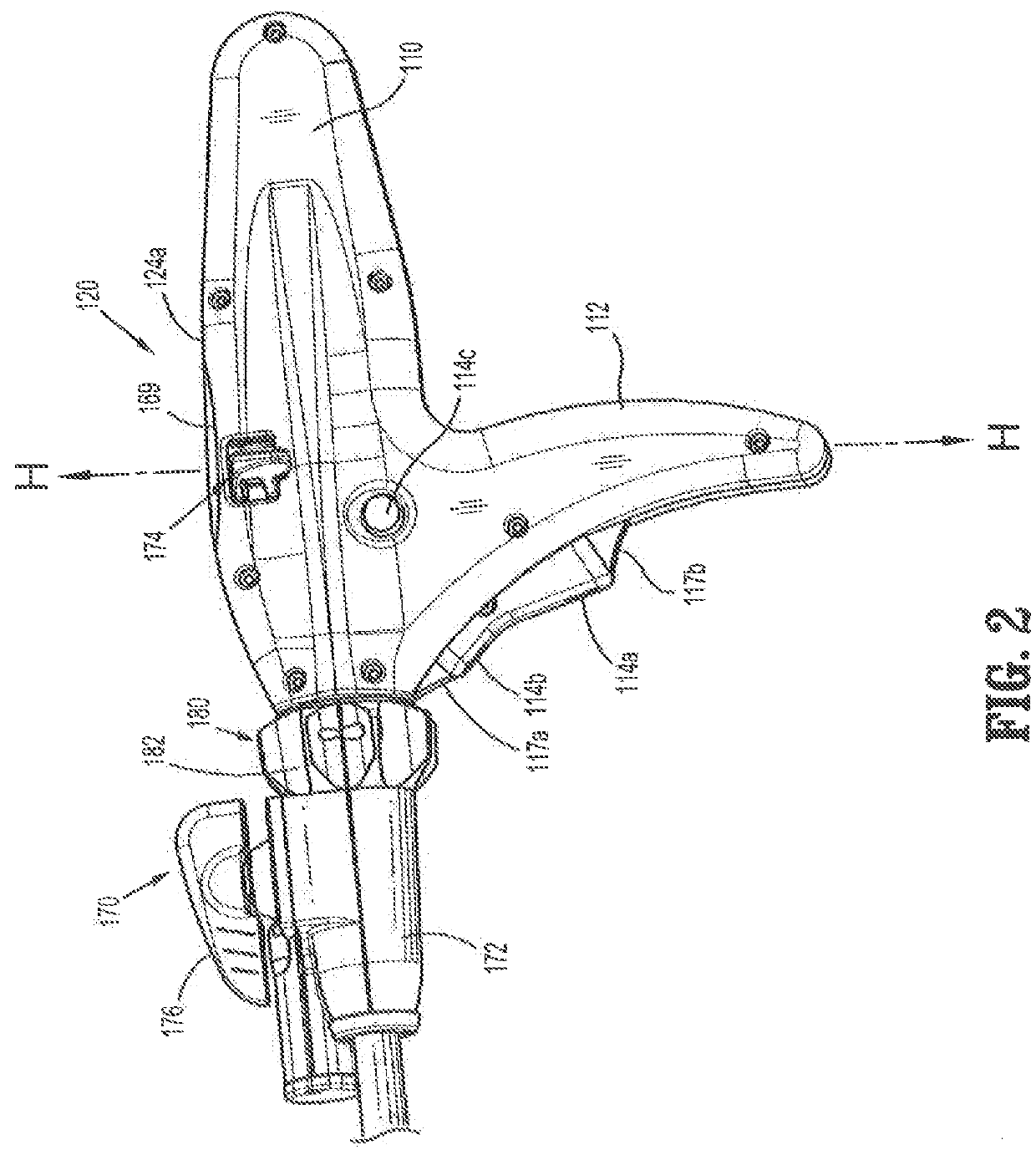
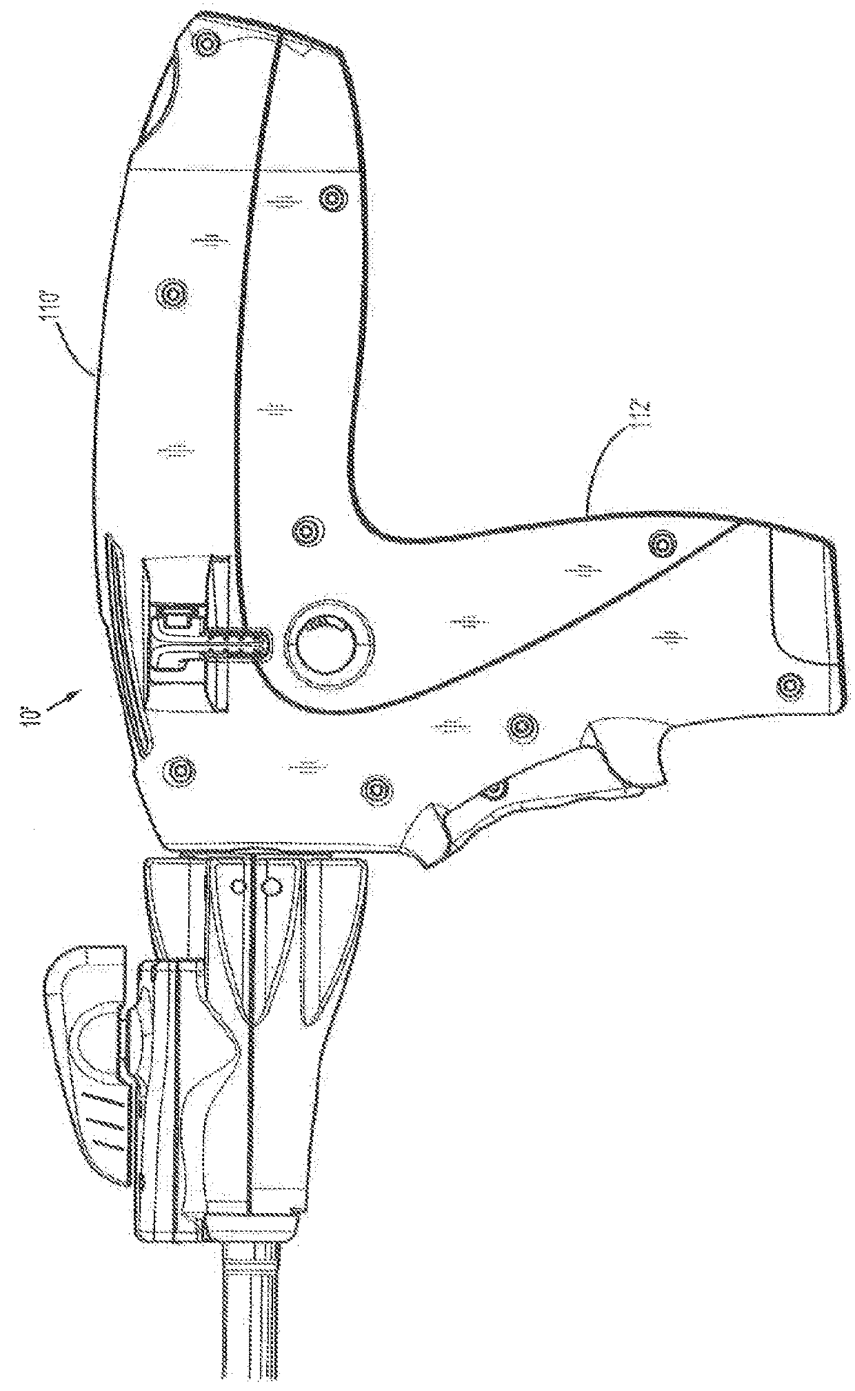
[0063]Embodiments of the presently disclosed powered surgical instrument are now described in detail with reference to the drawings, in which like reference numerals designate identical or corresponding elements in each of the several views. As used herein the term “distal” refers to that portion of the powered surgical instrument, or component thereof, farther from the user while the term “proximal” refers to that portion of the powered surgical instrument or component thereof, closer to the user.

[0064]Additionally, in the drawings and in the description that follows, terms such as “front”, “rear”, “upper”, “lower”, “top”, “bottom” and the like are used simply for convenience of description and are not intended to limit the disclosure thereto.

[0065]A powered surgical instrument, e.g., a surgical stapler, in accordance with the present disclosure is referred to in the figures as reference numeral 10. Referring initially to FIG. 1, powered surgical instrument 10 includes a housing 11...


PUM


Abstract

A calibration method for a hand-held surgical instrument is disclosed. The hand-held instrument includes a drive motor, a firing rod controlled by the drive motor and having at least one indicator, and a sensor configured to detect the at least one indicator. A microcontroller includes a pulse modulation algorithm stored therein to control the drive motor. The microcontroller executes a calibration algorithm to adjust at least one program coefficient in the pulse modulation algorithm.

Description

CROSS-REFERENCE TO RELATED APPLICATIONS[0001]This application is a continuation-in-part of U.S. patent application Ser. No. 12 / 895,897, filed on Oct. 1, 2010, which claims priority to U.S. Provisional Patent Application Ser. No. 61 / 248,971, filed on Oct. 6, 2009, and to U.S. Provisional Patent Application Ser. No. 61 / 248,504, filed on Oct. 5, 2009. U.S. patent application Ser. No. 12 / 895,897, filed on Oct. 1, 2010, is a continuation-in-part, of U.S. patent application Ser. No. 12 / 189,834, filed on Aug. 8, 2008, which claims priority to U.S. Provisional Patent Application Ser. No. 60 / 997,854, filed on Oct. 5, 2007. The entire contents of the above-mentioned applications are hereby incorporated by reference herein.BACKGROUND[0002]1. Technical Field[0003]The present disclosure relates to a surgical stapler for implanting mechanical surgical fasteners into the tissue of a patient, and, in particular, to a surgical stapler which is powered by a motor for firing surgical fasteners into ti...

Claims


Application Information

Patent Timeline
Patent Type & Authority Patents(United States)
IPC IPC(8): A61B17/072G01D18/00A61B17/29A61B17/32A61B90/00A61B17/00
CPCG01D18/008A61B17/07207A61B2090/0811A61B2017/00017A61B2017/00022A61B2017/00084A61B2017/00119A61B2017/00154A61B2017/00181A61B2017/00199A61B2017/00367A61B2017/00393A61B2017/00398A61B2017/00464A61B2017/00473A61B2017/00477A61B2017/00482A61B2017/00725A61B2017/00734A61B2017/2927A61B2017/2931A61B2017/320052A61B17/00234A61B2560/0223A61B2560/04
Inventor ZEMLOK, MICHAEL A.
Owner COVIDIEN LP
Why Eureka
Try Eureka