System, method, and module for RF-signal coverage for automotive vehicles

a technology for automotive vehicles and signal transmission, applied in power management, duplex signal operation, transportation and packaging, etc., can solve the problems of reducing the number of antennas and/or the length of rf cabling used to provide rf signal transmission inside and outside an automotive vehicle, reducing the data speed or throughput, and reducing the signal quality

Active Publication Date: 2018-08-07
MURATA MFG CO LTD
View PDF20 Cites 0 Cited by
  • Summary
  • Abstract
  • Description
  • Claims
  • Application Information

AI Technical Summary

Benefits of technology

[0010]To overcome the problems described above, preferred embodiments of the present invention provide a system, method, and module for providing RF-signal coverage both outside and inside of an automotive vehicle. According to the preferred embodiments of the present invention, the number of antennas and / or the length of RF cabling used to provide RF-signal coverage inside and outside an automotive vehicle are reduced according to the arrangement of an RF radiating cable and / or a directional coupler. Thus, communication is performed both inside and outside of the automotive vehicle at the same time, without any significant reduction in data speed or throughput.
[0011]Further, the preferred embodiments of the present invention provide RF-signal coverage both outside and inside of an automotive vehicle in a cost-effective manner.

Problems solved by technology

However, a device 111, such as an RF combiner, divider, or splitter, an example of which is shown in FIG. 7, typically has high insertion loss and low isolation between the outside antenna 101 and inside antenna 102, which reduces signal quality and causes a loss of throughput and a decrease in connection distances.
Furthermore, the above-described methods for providing RF-signal coverage both outside and inside of an automotive vehicle require two different antennas and a substantial length of RF cabling, which leads to high cost and complexity for implementing such methods.
Although known RF radiating cables provide RF-signal coverage for tunnels or buildings, for example, RF radiating cables have not been designed or arranged to provide antennas for automotive vehicle applications.

Method used


Image

  • System, method, and module for RF-signal coverage for automotive vehicles
  • System, method, and module for RF-signal coverage for automotive vehicles
  • System, method, and module for RF-signal coverage for automotive vehicles

Examples


Embodiment Construction

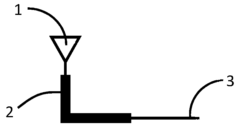
[0028]According to a first preferred embodiment of the present invention as shown in FIGS. 1-3, only one antenna is required to cover both the outside and inside of an automotive vehicle. The single antenna includes, at one end, an outside antenna 1 that is preferably a typical antenna, which include, for example, whip antenna, rod antenna, or shark fin antenna, and, at the other end, an inside antenna 2 that is an RF radiating cable. One end of the inside antenna 2 can be connected to an RF port 3. RF-signal coverage for inside of the automotive vehicle is provided by the inside antenna 2 to cover inside the automotive vehicle and operate as an antenna. The wireless coverage outside of the automotive vehicle is preferably covered by the outside antenna 1. According to this arrangement as shown in FIG. 1, only one RF cable is required for RF-signal coverage of both the outside and the inside of the automotive vehicle, and a single antenna covers both areas.

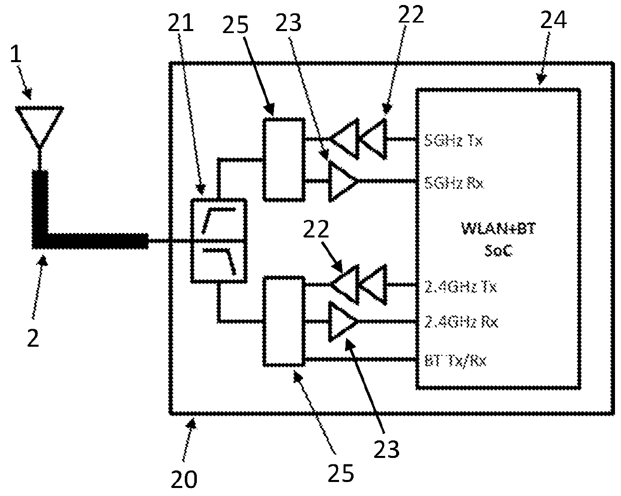
[0029]FIG. 2 shows a wirel...


PUM


Abstract

An antenna system for an automotive vehicle includes an outside antenna that is located outside of the automotive vehicle, an inside antenna that includes an RF radiating cable and that is located inside of the automotive vehicle, and a wireless communication module. The inside antenna is connected between the outside antenna and the wireless communication module such that all signals received and transmitted by the outside antenna are received and transmitted through the inside antenna.

Description

BACKGROUND OF THE INVENTION[0001]1. Field of the Invention[0002]The present invention relates to providing RF-signal coverage for vehicles, and more specifically, the present invention relates to providing RF-signal coverage both inside and outside of an automotive vehicle at the same time.[0003]2. Description of the Related Art[0004]Recent developments in networking and automotive technologies have resulted in the desire to provide RF-signal coverage both inside and outside an automotive vehicle. Various techniques have been attempted to implement RF-signal coverage both inside and outside of automotive vehicles, in particular, to address the problems associated with the bodies of automotive vehicles, which are typically made of metal and thus provide electromagnetic shields that separate the two desired RF-signal coverage areas.[0005]Known methods of providing RF-signal coverage both inside and outside of an automotive vehicle include simply using an RF combiner or an RF switch to...

Claims


Application Information

Patent Timeline
Patent Type & Authority Patents(United States)
IPC IPC(8): H04M1/00H04B1/00H04L5/14H04W52/52H04B7/04H04W4/40
CPCH04W4/40H04B7/04H04W52/52H04L5/14H04B1/0057H04B1/1009H04B1/3822
Inventor KIMOCHII, AKIHIRO
Owner MURATA MFG CO LTD
Why Eureka
Try Eureka