
Magnetic data embedding apparatus having checking function

a technology of magnetic data and embedding apparatus, which is applied in the direction of maintaining head carrier alignment, digital recording, instruments, etc., can solve the problems of reducing the time for writing and checking. , the effect of reducing the rotational speed of the magnetic disk or the number of magnetic disks in the stack

Inactive Publication Date: 2005-10-11
FUJI ELECTRIC CO LTD
View PDF8 Cites 10 Cited by
  • Summary
  • Abstract
  • Description
  • Claims
  • Application Information

AI Technical Summary

Benefits of technology

[0027]Accordingly, an object of the invention is to provide a magnetic data embedding apparatus having a checking function, that provides increased accuracy in writing magnetic data on a stack of magnetic disks by virtue of having an accuracy in position detection not limited by a degree of resolution of a rotary encoder, and that allows the time for the processes from the start of writing to the end of checking to be reduced. Such an apparatus must provide these improvements without a reduction in either the rotational speed of the magnetic disks or the number of magnetic disks in the stack.
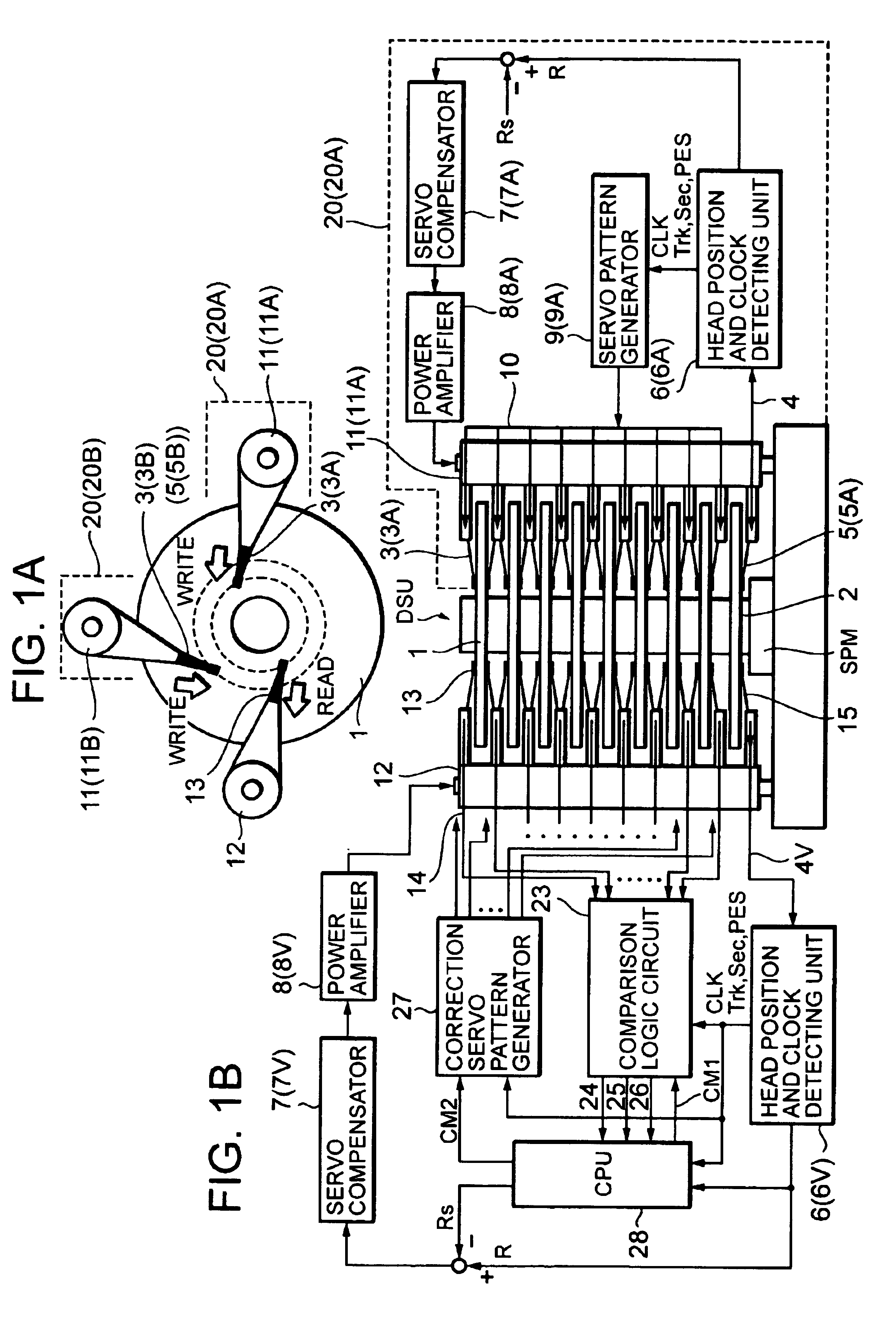
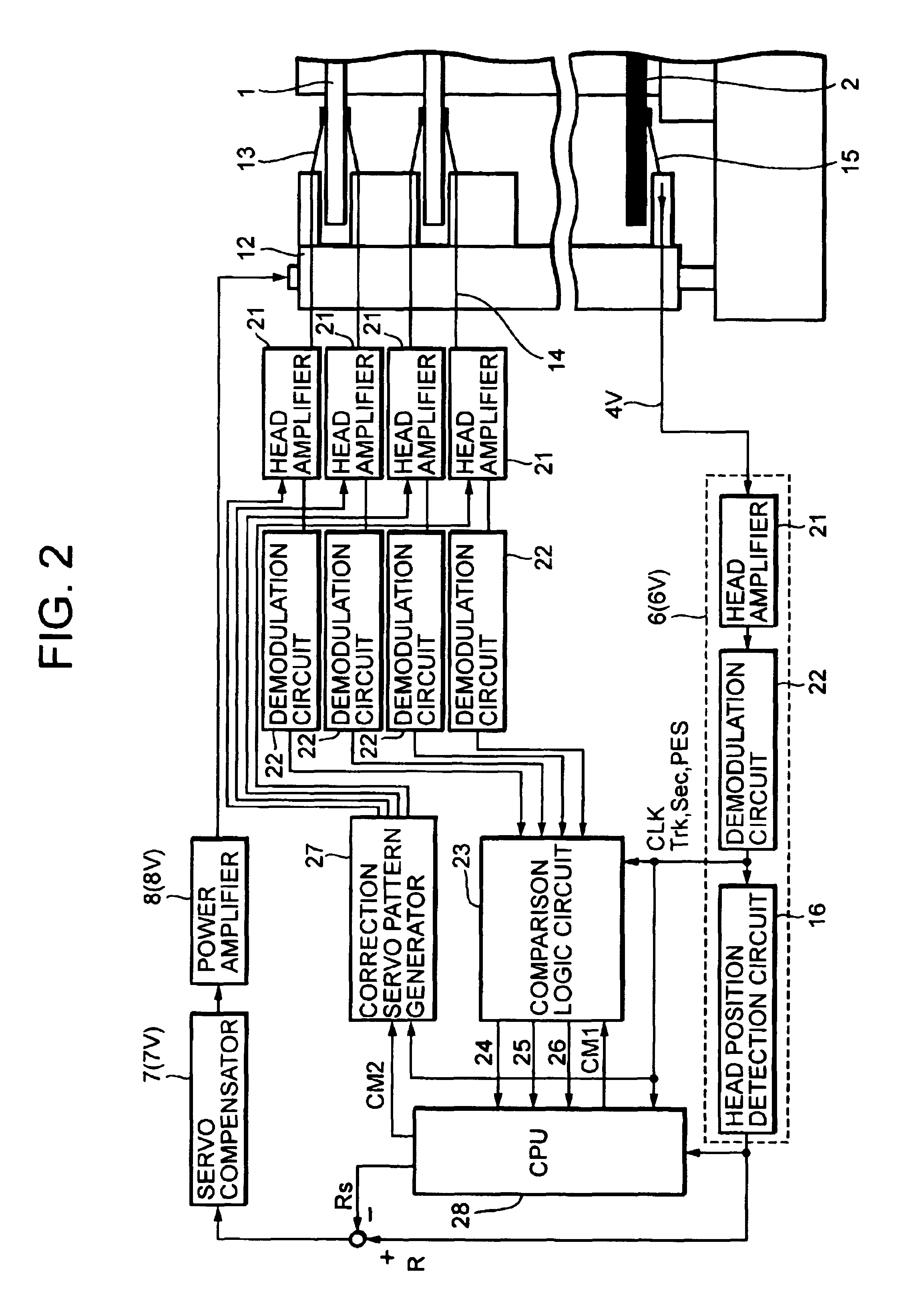
[0032]In more detail, the magnetic data embedding apparatus additionally includes, corresponding to each surface of the object disks, a comparison means (including a comparison logic circuit and a CPU). The comparison means compares the embedded data read out from the surface of the object disk by the second type checking head, with the magnetic data read out by the first type checking head simultaneously with writing operation of the write magnetic heads. Thus, the contents in the master disk can be exactly written on every object magnetic disks. Moreover, the total time required by the processes from start of writing to end of checking can be reduced.

Problems solved by technology

With increases in track density on magnetic disks, the time required for the writing operation increases, resulting in lower throughput.
This checking time also increases like the writing time, thus further decreasing the throughput.
By increasing the rotational speed of disks, the time for writing and checking can be reduced, but such increases in speed increases mechanical vibration.
The vibration makes it difficult to write accurate servo pattern.
Thus, there is tradeoff between speed and vibration.
This causes precision of rotation to deteriorate.
Since the number of stacked magnetic heads must also increase, it becomes difficult to assure that a specified degree of accuracy is reached in attaching the magnetic heads.
As recording density increases, the required accuracy in detecting the position of the magnetic heads may exceed the resolution precision of the rotary encoder.

Method used


Image

  • Magnetic data embedding apparatus having checking function
  • Magnetic data embedding apparatus having checking function
  • Magnetic data embedding apparatus having checking function

Examples


first embodiment

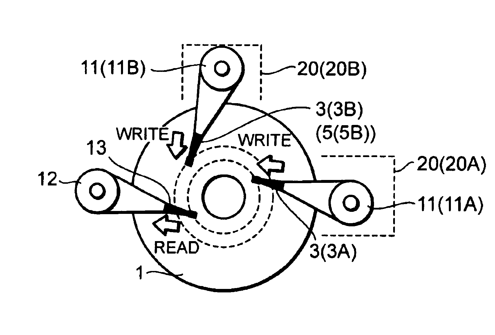
[0057]FIG. 6 is a timing chart illustrating operation of the writing side functional sections of a magnetic data embedding apparatus having checking function according to the Line (a) of FIG. 6 is the same as line (b) of FIG. 5, and shows the magnetic data signals 4 from the master disk 2. Line (b) of FIG. 6 shows clock CLK regenerated from the portion of the clock pattern PC1 in the magnetic data signals 4. Line (c) of FIG. 6 shows binarized signals of the magnetic data signals 4. Line (d) of FIG. 6 shows track address Trk, sector address Sec, and precise position PES that are detected (demodulated) from the binarized signals of line (c) of FIG. 6. Line (e) of FIG. 6 shows magnetic pattern signals 10 being written to the magnetic disk 1.

[0058]Operation of the writing side sections in FIG. 1B will be described with reference to FIG. 6. The operation is performed by the head stack servo unit 20A or 20B in the range of tracks that is assigned to the servo unit 20A or the servo unit 2...

second embodiment

[0078]FIG. 3 shows a structure of a magnetic data embedding apparatus having a checking function according to the invention. The essential difference between the magnetic data embedding apparatus of FIG. 3 and the corresponding apparatus of FIG. 1 is that the apparatus of FIG. 3 has one writing side rotary positioner 11W rather than the two rotary positioners 11A and 11B. The rotary positioner 11W in FIG. 3 has a plurality of read magnetic heads 5 (four in this example, 51 through 54) arranged along a nearly radial direction at regular intervals on the master disk 2 for access thereto. The rotary positioner 11W also has the same number of servo heads 3 (four in this example, 31 through 34) for each surface of the magnetic disks 1, arranged along nearly radial direction at regular intervals on the magnetic disk surfaces, for access thereto. The read magnetic heads 5 and the servo heads 3 are integrally stacked and pivotally supported on the rotary positioner 11W.

[0079]The read magnet...


PUM


Abstract

Rotary positioners integrally and pivotally stack a read magnetic head for reading a master disk and servo heads for writing to each surface of magnetic disks, the master disk and magnetic disks being stacked on a shaft of a spindle motor. Every surface of every magnetic disk is written by the servo heads in parallel while sharing a range of tracks. Simultaneously with the writing, checking magnetic heads stacked on a checking-dedicated rotary positioner read written data on the master disk and on each surface of the magnetic disks. A comparison logic circuit compares the read data from the magnetic disk surfaces with the data from the master disk. If an inconsistency is found, the contents of the master disk are overwritten on the corresponding magnetic disk surface through a correction servo pattern generator by the checking magnetic head.

Description

CROSS-REFERENCE TO RELATED APPLICATIONS[0001]The entire disclosure of the inventors' corresponding Japanese patent application, Serial No. JP PA 2003-071929 filed Mar. 17, 2003, is incorporated by reference.BACKGROUND OF THE INVENTION[0002]1. Field of the Invention[0003]The invention relates to a magnetic data embedding apparatus to write magnetic data (or embedded data) into a magnetic disk. More particularly, the invention relates to such an apparatus, which includes a servo pattern for detecting a magnetic head position, an ID pattern for identifying a magnetic disk, and a program into a virgin or unwritten magnetic disk.[0004]In more detail, a magnetic data embedding apparatus according the invention is used in connection with writing data into a magnetic disk to meet customer requirements and so produce a product magnetic disk. The magnetic data embedding apparatus is also called a disk servo writer. Such a magnetic data embedding apparatus includes a master disk and a pluralit...

Claims


Application Information

Patent Timeline
IPC IPC(8): G11B27/30G11B5/596G11B21/10
CPCG11B5/59633G11B27/3027
Inventor SATO, NARUMISATO, KIMINORI
Owner FUJI ELECTRIC CO LTD
Learn More