Card edge connector

a card edge connector and connector technology, applied in the direction of coupling device connection, coupling/disconnecting parts, electrical apparatus, etc., can solve the problems of affecting the quality stability and service life of the whole card edge connector, the plastic connection strength between the rotating shafts at two sides of the main body is insufficient, and the rotating shafts are easy to break from the main body. , to achieve the effect of improving the bearing capacity of the plastic ear clip, improving the connection strength, and improving the bearing capacity

Active Publication Date: 2018-08-21
LOTES
View PDF15 Cites 4 Cited by
  • Summary
  • Abstract
  • Description
  • Claims
  • Application Information

AI Technical Summary

Benefits of technology

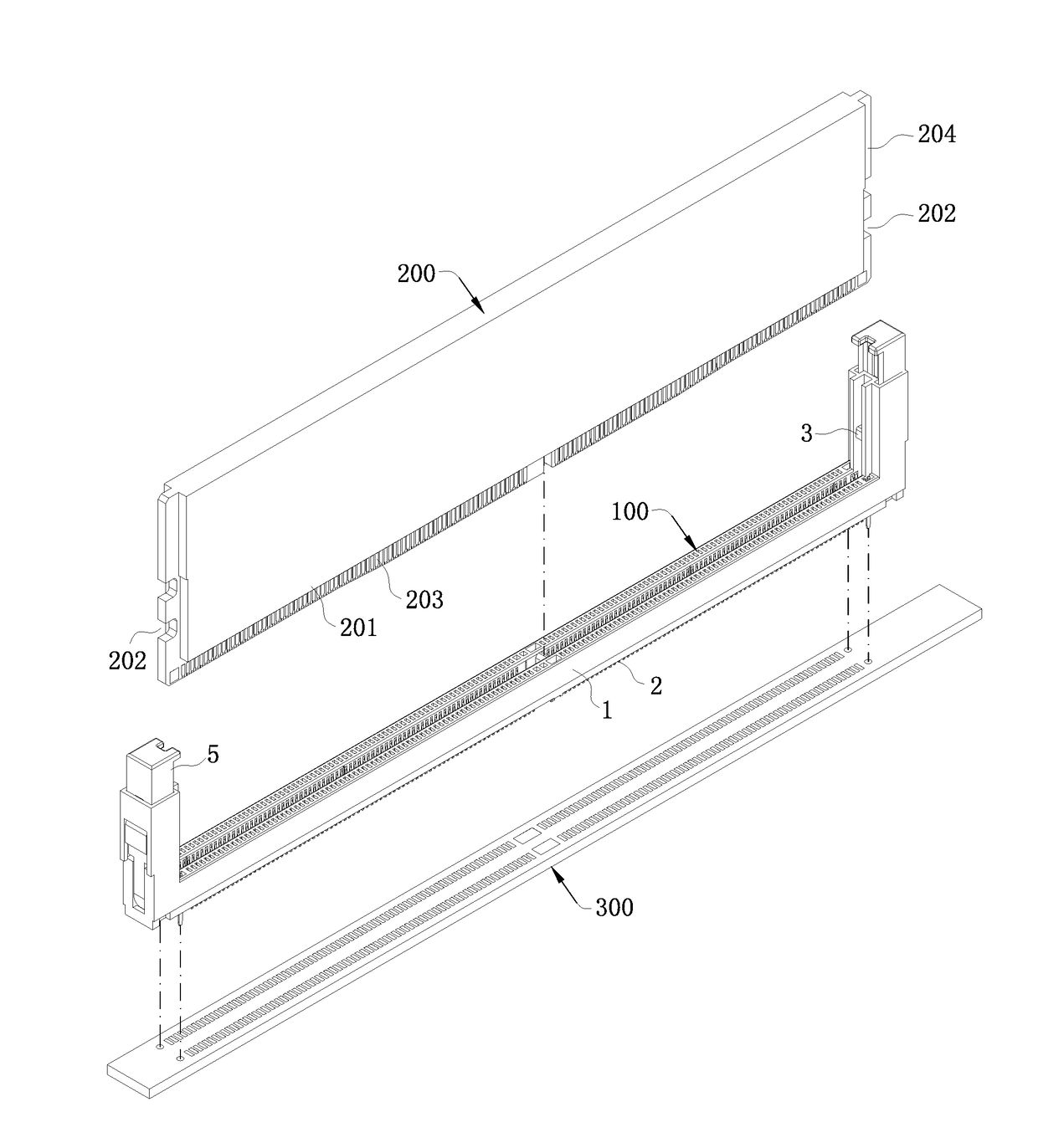
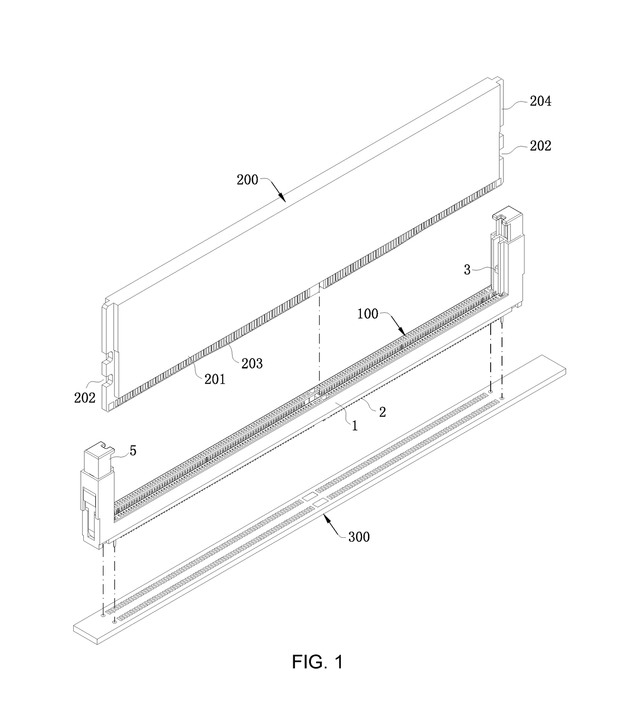
[0008]In one aspect, the present invention relates to a card edge connector that ensures the miniaturization of products, and also ensures the plastic ear clips having high bearing capacity and being uneasy to break, and can prevent the breakage of the rotating shafts under force.
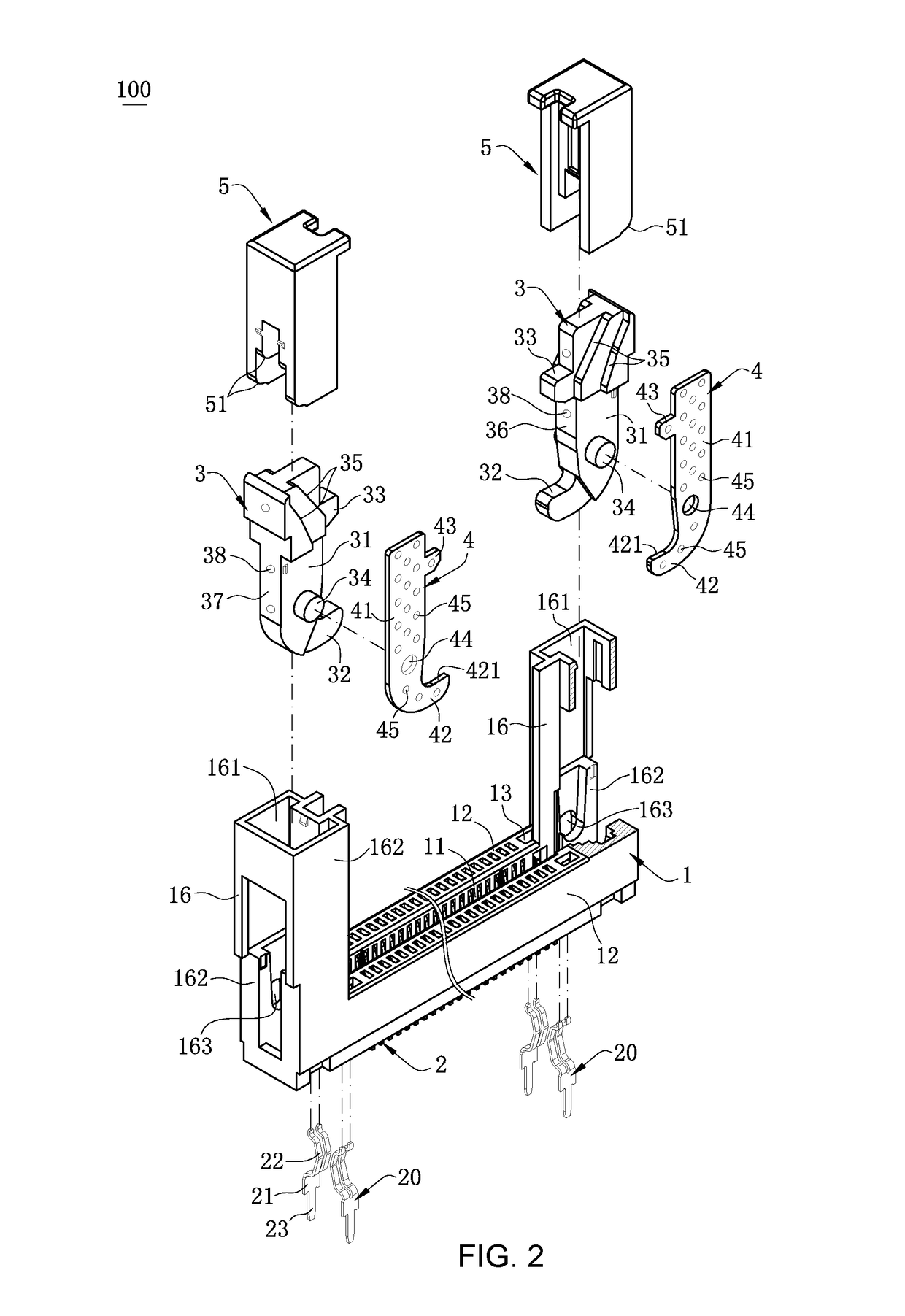
[0025]Compared with the related art, the metal reinforcing member of the present invention is embedded in the plastic ear clip, and the metal reinforcing member extends in the main body and the withdrawing portion, so that the existence of the metal reinforcing member improves the connection strength between the main body and the withdrawing portion, i.e. the bearing capacity of the plastic ear clip is improved, and the withdrawing portion is uneasy to break when the withdrawing portion pushes the electronic card to be withdrawn from the slot. Moreover, the metal reinforcing member has the first through hole, the first through hole is arranged at the position corresponding to the rotating shafts, and when the plastic ear clip is injection molded, plastics formed in the first through hole are integrally connected with the plastics at two sides of the metal reinforcing member, so the connection strength between the rotating shafts at two sides of the plastic ear clip can be improved, and the rotating shaft can be prevented from breaking from the main body under a force.

Problems solved by technology

In actual use, the withdrawing portion may break due to the insufficient bearing capacity, thus further influencing the quality stability and the service life of the whole card edge connector.
However, when the metal sheet is embedded in the ear clip, as the metal sheet is not provided with a through hole at the position corresponding to the rotating shafts, plastics at two sides of the metal sheet are divided into two halves at the positions of the rotating shafts, thus, the plastic connection strength between the rotating shafts at two sides of the main body is insufficient, and in the card withdrawing process, the rotating shafts are easy to break from the main body when being subjected to a force.
Therefore, a heretofore unaddressed need exists in the art to address the aforementioned deficiencies and inadequacies.

Method used


Image

  • Card edge connector
  • Card edge connector
  • Card edge connector

Examples


Embodiment Construction

[0035]The present invention is more particularly described in the following examples that are intended as illustrative only since numerous modifications and variations therein will be apparent to those skilled in the art. Various embodiments of the invention are now described in detail. Referring to the drawings, like numbers indicate like components throughout the views. As used in the description herein and throughout the claims that follow, the meaning of “a”, “an”, and “the” includes plural reference unless the context clearly dictates otherwise. Also, as used in the description herein and throughout the claims that follow, the meaning of “in” includes “in” and “on” unless the context clearly dictates otherwise. Moreover, titles or subtitles may be used in the specification for the convenience of a reader, which shall have no influence on the scope of the present invention.

[0036]It will be understood that when an element is referred to as being “on” another element, it can be di...


PUM


Abstract

A card edge connector includes an insulating body, multiple terminals arranged at the insulating body, plastic ear clips, and metal reinforcing members embedded in the plastic ear clips. The insulating body has a slot extending along a lengthwise direction for inserting an electronic card. Each terminal has a contact portion protruding into the slot to connect the electronic card. Each plastic ear clips has a main body and a withdrawing portion disposed below the main body. The plastic ear clip has two rotating shafts at two opposite sides of the main body. The rotating shafts are pivoted to the insulating body. The withdrawing portion is used for pushing the bottom end of the electronic card to be separated from the slot. The metal reinforcing members extend in the main body and the withdrawing portions, and has a first through hole arranged at a position corresponding to the rotating shafts.

Description

CROSS-REFERENCE TO RELATED APPLICATION[0001]This application claims priority and the benefit of U.S. Provisional Application No. 62 / 361,720, filed on Jul. 13, 2016, the entire contents of which are hereby incorporated by reference.FIELD OF THE INVENTION[0002]The present invention relates generally to a card edge connector, and more particularly to a card edge connector that can improve the bearing capacity of plastic ear clips and can prevent rotating shafts from breaking under forces.BACKGROUND OF THE INVENTION[0003]Known card edge connectors are used for connecting electronic cards. The card edge connector includes a slender insulating body, multiple terminals and a pair of ear clips. The insulating body has a slot which is used for inserting the electronic card, and the multiple terminals are arranged at two sides of the slot. The insulating body is provided with a mounting portion at each of two ends of the slot, and the ear clips are installed in the mounting portions. Each ear...

Claims


Application Information

Patent Timeline
Patent Type & Authority Patents(United States)
IPC IPC(8): H01R13/62H01R12/72H01R13/629
CPCH01R12/721H01R13/62938H01R12/737H01R12/7005
Inventor CAI, YOU HUA
Owner LOTES
Why Eureka
Try Eureka