Liquid ejecting apparatus

a technology of liquid ejecting apparatus and liquid container, which is applied in the direction of printing, etc., can solve the problems of difficult difficulty in visual recognition of mounting failure of liquid container, and achieve the effect of facilitating visual recognition of mounting failur

Active Publication Date: 2018-08-28
SEIKO EPSON CORP
View PDF11 Cites 0 Cited by
  • Summary
  • Abstract
  • Description
  • Claims
  • Application Information

AI Technical Summary

Benefits of technology

[0008]An advantage of some aspects of the invention is that a liquid ejecting apparatus that facilitates visual recognition of a mounting failure of the liquid container is provided.
[0010]The liquid ejecting apparatus according to the above aspect, the wall sections are preferably not arranged in a height order in an arrangement direction of the plurality of liquid containers. Accordingly, a difference in the lifted amounts of the liquid containers adjacent to each other is increased, thereby facilitating visual recognition of a mounting failure.
[0011]Further, it is preferred that the holder is movable in a direction perpendicular to a transportation direction of the medium, the plurality of liquid containers are arranged side by side in the transportation direction, and the wall section which corresponds to the liquid container located at a most upstream position in the transportation direction has a highest height. Accordingly, a mounting failure of the liquid container located at a position difficult to be visually recognized can be easily recognized.

Problems solved by technology

However, when the liquid container is mounted on the holder, there is a case where incomplete mounting is erroneously recognized as complete mounting, which causes a problem that a mounting failure is difficult to be visually recognized.
Although erroneous insertion of the liquid container can be prevented by providing a feature that prevents erroneous insertion of the liquid container on the bottom of the holder as disclosed in JP-A-2014-28499, visual recognition of mounting failure of the liquid container is still difficult.
Such a problem is not limited to ink jet recording apparatuses, but also occurs in liquid ejecting apparatuses that eject liquid other than ink.

Method used


Image

  • Liquid ejecting apparatus
  • Liquid ejecting apparatus
  • Liquid ejecting apparatus

Examples


embodiment 1

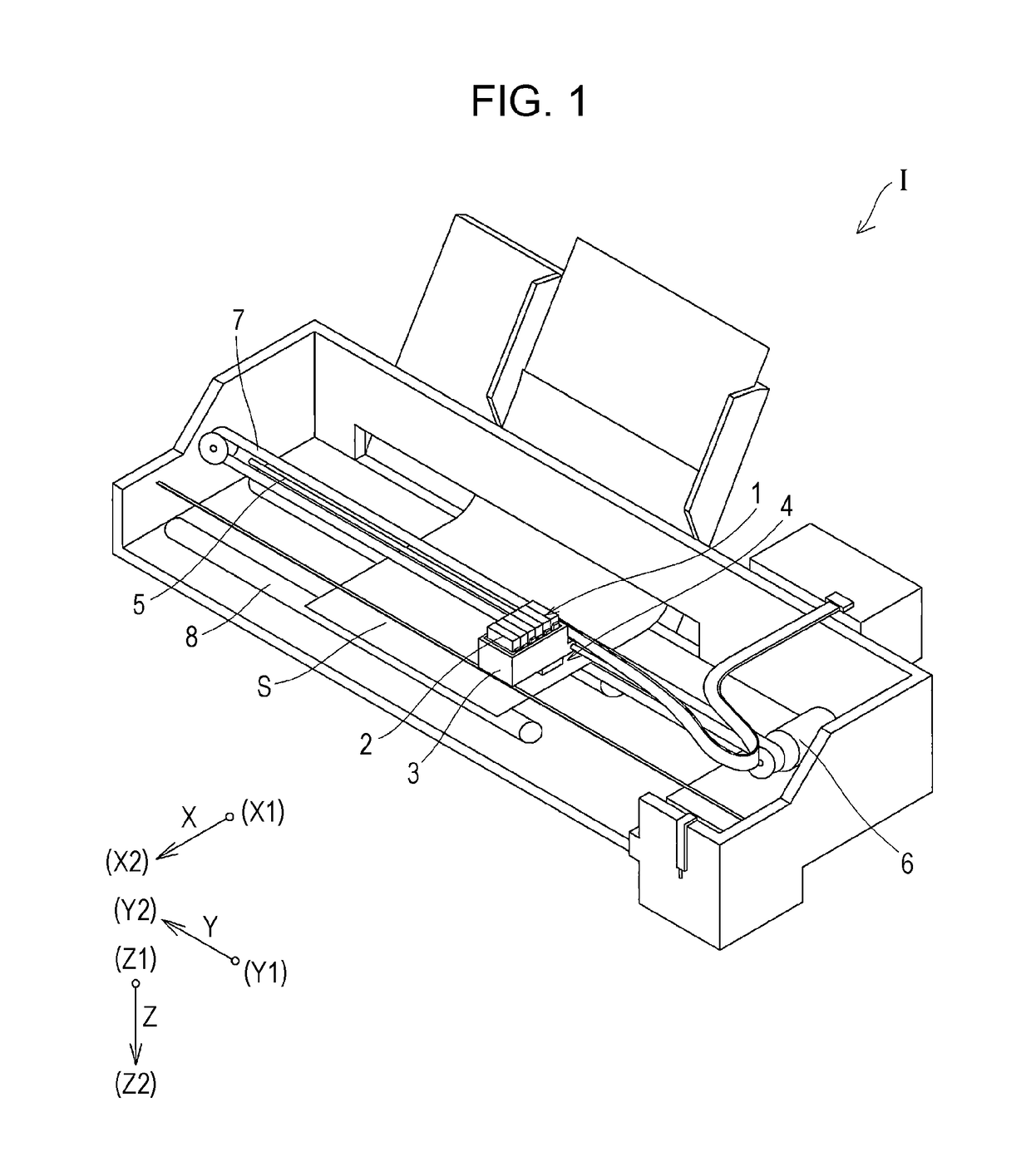
[0024]The invention will be described in detail with reference to an embodiment. FIG. 1 is a schematic configuration view of an ink jet recording apparatus which is an example of a liquid ejecting apparatus according to Embodiment 1 of the invention.

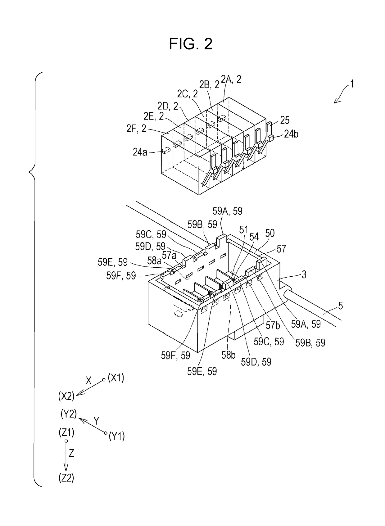
[0025]As shown in FIG. 1, an ink jet recording apparatus I which is an example of a liquid ejecting apparatus of the present embodiment includes an ink jet recording head unit 1 (hereinafter, simply referred to as a head unit 1), which is a liquid ejecting head unit that ejects ink in the present embodiment. The head unit 1 is provided with a cartridge 2 which is a liquid container that stores ink as liquid. The cartridge 2 is detachably attached in the head unit 1. The cartridge 2 may be of a type that stores one type of ink, or alternatively, may be of a type that stores a plurality of types of ink. A plurality of cartridges 2, that is, two or more cartridges 2 are detachably fixed to the head unit. The head unit 1 and the cartridges 2...


PUM


Abstract

A liquid ejecting apparatus includes, a liquid ejecting head that ejects liquid onto a medium, a plurality of liquid containers 2 that stores liquid which is supplied to the liquid ejecting head, the liquid containers 2 being provided with protrusions 24a and 24b, and a holder 50 that carries the plurality of liquid containers 2, the holder including wall sections 57 and recesses 58a and 58b disposed inside the wall sections 57 into which the protrusions 24a and 24b of each of the plurality of liquid containers 2 are inserted, wherein the wall sections 57 at least adjacent to one another have different heights corresponding to the plurality of liquid containers 2.

Description

[0001]This application claims priority under 35 U.S.C. § 119 to Japanese Patent Application No. 2016-185197 filed on Sep. 23, 2016, the entire disclosure of which is expressly incorporated by reference herein.BACKGROUND1. Technical Field[0002]The present invention relates to a liquid ejecting apparatus which includes a liquid ejecting head that ejects liquid, and a holder that holds a liquid container which supplies liquid to the liquid ejecting head, and more specifically, an ink jet recording apparatus that ejects ink as the liquid.2. Related Art[0003]A liquid ejecting apparatus which is typically an ink jet recording apparatus such as an ink jet printer and a plotter includes a head unit that is configured to eject liquid as liquid droplets from a cartridge which is a liquid container that stores liquid such as ink, and a carriage that holds the cartridge together with the head unit.[0004]For example, JP-A-2014-28499 discloses a configuration in which projections are provided on ...

Claims


Application Information

Patent Timeline
Patent Type & Authority Patents(United States)
IPC IPC(8): B41J2/175
CPCB41J2/17553B41J2/1752B41J2/21B41J2/17509B41J2/17523B41J2/17563B41J2/19
Inventor KOBAYASHI, HARUKI
Owner SEIKO EPSON CORP
Why Eureka
Try Eureka