Method and assembly for the connection of two tubular members

a technology for connecting two tubular members and tubular joints, which is applied in the direction of sleeves/socket joints, pipe joints, couplings, etc., can solve the problems of reducing the use of the connection assembly of the known type described above and not being easy to use or replace, so as to achieve the effect of simple and cheap implementation

Active Publication Date: 2018-08-28
RPE
View PDF11 Cites 0 Cited by
  • Summary
  • Abstract
  • Description
  • Claims
  • Application Information

AI Technical Summary

Benefits of technology

[0007]It is an object of the present invention to provide an assembly for the connection of two tubular members which is free from the drawbacks described above and which is simple and cheap to implement.
[0009]Thanks to the present invention, the connection sleeve can be easily inserted at the end of the tubular member to be connected.

Problems solved by technology

Consequently, the connection assembly of the known type described above is of a reduced use and is not easy to use or replace in particular when the first tubular member is relatively long.

Method used


Image

  • Method and assembly for the connection of two tubular members
  • Method and assembly for the connection of two tubular members
  • Method and assembly for the connection of two tubular members

Examples


Embodiment Construction

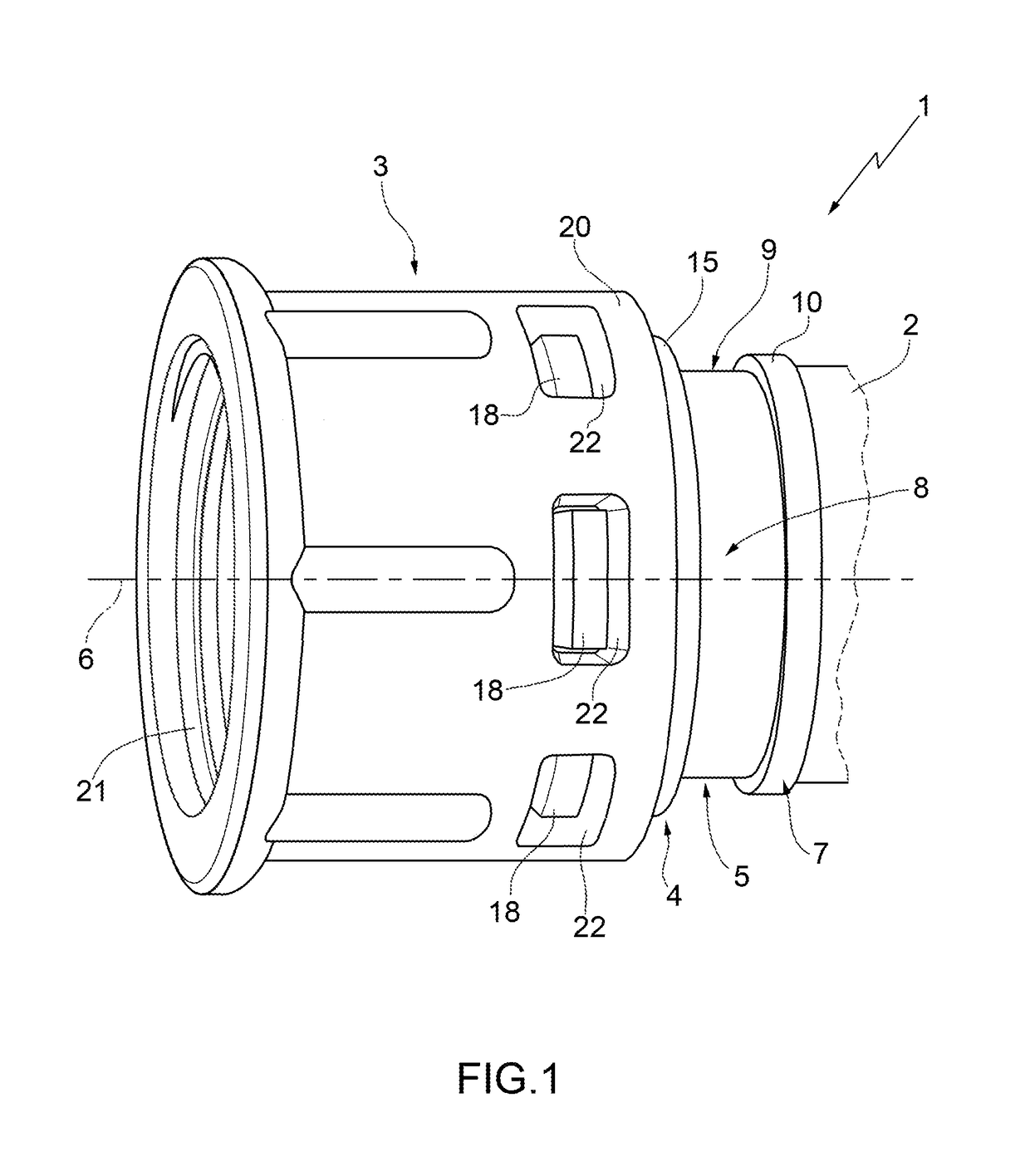
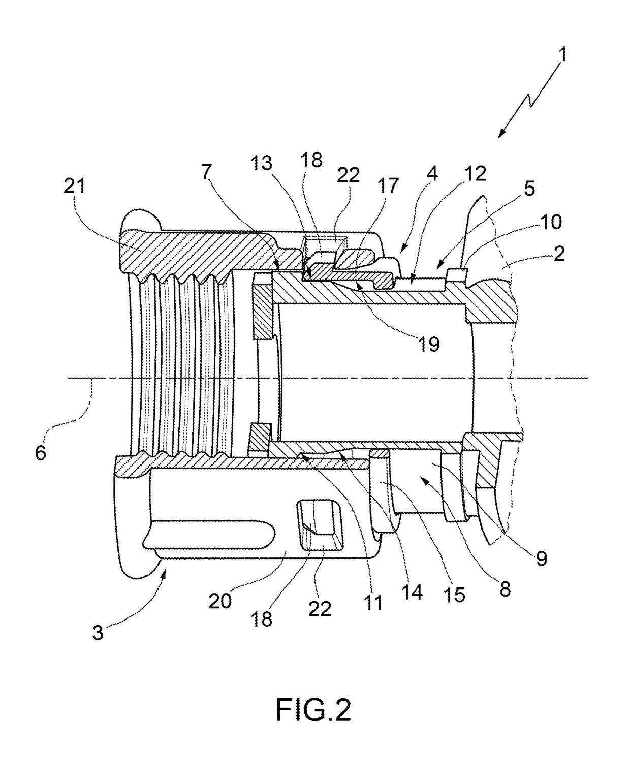
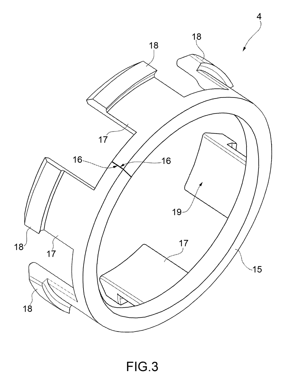
[0029]With reference to FIGS. 1 and 2, with 1 is indicated, as a whole, a connection assembly for tubular members comprising a first tubular member 2; a connection sleeve 3 which can be coupled to the tubular member 2 and configured to be coupled to a second tubular member (not shown); and an intermediate coupling ring 4 mounted onto the tubular member 2 to lock the sleeve 3 to the tubular member 2 itself.

[0030]The tubular member 2 can be, for example, a valve body of a valve, a fitting, or a manifold, while the sleeve 3 may be, for example, a threaded nut ring or a bayonet fitting.

[0031]The tubular member 2 comprises an end segment 5, which has a longitudinal axis 6, is delimited by an outer surface 7 substantially coaxial with the axis 6, and has a shaped annular cavity 8, extending around the axis 6, and which opens outwards at the surface 7.

[0032]The cavity 8 defines onto the tubular member 2 a coupling portion 9, which is engaged in a sliding manner by the ring 4, and is axiall...


PUM


Abstract

An assembly for the connection of tubular members is provided with a connection sleeve which is suited to connect one to the other a first tubular member and a second tubular member, and an intermediate coupling ring mounted to slide along at least an intermediate coupling portion of the first tubular member; the coupling portion having a diameter ranging from a minimum to a maximum so that the sliding of the coupling ring (4) along the coupling portion causes the deformation of the coupling ring in a locking configuration of the connection sleeve to the first tubular member.

Description

CROSS REFERENCE TO RELATED APPLICATIONS[0001]The present application is a U.S. National Phase of International Patent Application PCT / IB2014 / 059137 filed on Feb. 20, 2014, which claims priority to Italian Application No. MI2013A000240, filed on Feb. 20, 2013, each of which is incorporated by reference as if expressly set forth in their respective entireties herein.TECHNICAL FIELD[0002]The present invention relates to an assembly for the connection of two tubular members.BACKGROUND ART[0003]In particular, the present invention relates to a connection assembly comprising a connection sleeve, for example a threaded ring nut, mounted on a first tubular member and connectable to a second tubular member.[0004]The connection sleeve is arranged in abutment against an abutment formed at a free end of the first tubular member and for this reason has a minimum diameter which is smaller than the diameter of the abutment and greater than the maximum diameter of the remaining part of the first tu...

Claims


Application Information

Patent Timeline
Patent Type & Authority Patents(United States)
IPC IPC(8): F16L37/08F16L19/02F16L37/084F16L21/08
CPCF16L37/0847F16L21/08F16L19/0231
Inventor BERLUSCONI, GIORDANO
Owner RPE
Why Eureka
Try Eureka