
operating unit

A technology of operating units and components, applied to electrical components, including printed electrical components, program control, etc., can solve the problems of inflexible design and layout of operating units, and achieve the effect of simple and cheap implementation

Active Publication Date: 2019-01-22
SCHNEIDER ELECTRIC IND SAS
View PDF3 Cites 0 Cited by
  • Summary
  • Abstract
  • Description
  • Claims
  • Application Information

AI Technical Summary

Problems solved by technology

The design and arrangement of the operating unit is largely inflexible due to this system

Method used


Image

  • operating unit
  • operating unit
  • operating unit

Examples


Embodiment Construction

[0034] In the ensuing description, components that are the same or have the same effect are provided with the same reference numerals.

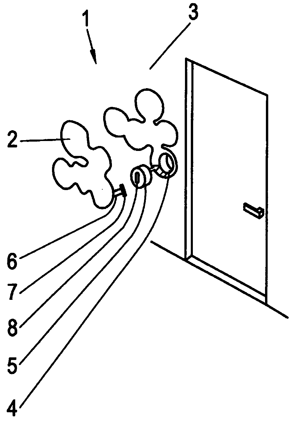
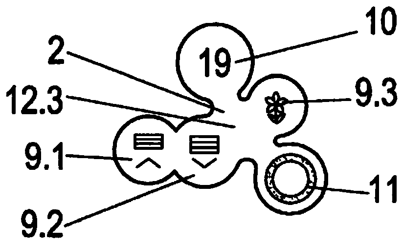
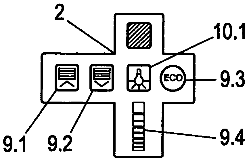
[0035] exist figure 1 A mounting device 1 is schematically shown in , which in the embodiment shown is a building services installation device with an operating unit 2 on the front side, wherein the different units are shown in exploded view. The mounting device 1 is fastened into a mounting socket 4 arranged in a building wall 3 . The installation device 1 has a communication plug 5 which acts as a control for consumer electronics (not shown). The operating unit 2 has different functional elements 9 - 11 which are connected in a wired manner to the communication plug 5 in order to allow an electrical supply and a technical signal supply. For this purpose, the functional elements within the operating unit 2 are connected to the coupling point 7 via a flexible conductor structure 6 in the form of a plug-in connection. Coupling points 8 in t...


PUM


Abstract

The invention relates to an operating unit of a mounting device comprising a communication plug-in for controlling electronic consumer goods. The operating unit has functional elements and the unit is wired and / or wirelessly connected to the communication plug for two-way communication transmission and / or for supplying voltage. The functional element comprises a printed electronic component which is mechanically flexible and which is located on a mechanically flexible carrier foil.

Description

technical field [0001] The invention relates to an operating unit. Background technique [0002] Operating units of electrical installations for controlling circuit elements or communication inserts are known in various forms, for example for building service engineering, for industrial plants and machines or also for switch rooms. The operating unit is typically a component of the installed device and is implemented either as a single compact device unit or as a modular device design. It is also known to arrange the operating unit separately from the circuit elements or communication plug-ins to be controlled, wherein technical signal communication and / or power supply takes place via a wired connection or via a wireless connection. Such an operating unit comprises various functional elements, by means of which various display and / or operating functions can be realized. [0003] The operating units are fixed with respect to their physical configuration (shape, color, desig...

Claims


Application Information

Patent Timeline
Patent Type & Authority Patents(China)
IPC IPC(8): H03K17/96G05B15/02H05K1/03H05K1/16
CPCG05B15/02G05B2219/25439G05B2219/2642H03K17/962
Inventor Y.塞弗林斯基E.塞尼乔尔特J·库纳特B·勒科内特
Owner SCHNEIDER ELECTRIC IND SAS
Learn More