Spill resistant warming drawer

a technology of drawers and drawer covers, which is applied in the direction of heating types, lighting and heating apparatus, and domestic stoves or ranges. it can solve the problems affecting the operation of the appliance, so as to prevent the electronic components from leaking into the appliance. the problem of the control area, the problem of liquid spilling over the drawers, and the effect of affecting the operation

Inactive Publication Date: 2018-09-04
HAIER US APPLIANCE SOLUTIONS INC D B A GE APPLIANCES
View PDF116 Cites 4 Cited by
  • Summary
  • Abstract
  • Description
  • Claims
  • Application Information

AI Technical Summary

Benefits of technology

[0010]in order to protect the controls within the control housing from liquid such as water spills, a first sealant may be included on each of the openings on the front portion of the chassis. The first sealant may include o-rings, rings, or flexible boots made from any material such as rubber or poly vinyl chloride. The first sealant forms a liquid-tight seal between the plurality of manual controls and the front portion of the chassis for preventing liquid from entering the control housing through the plurality of openings.
[0013]Inside the control housing, the plurality of controls is stored and controls all the functions of the appliance. The controls inside the control housing may include electronic circuit boards, wiring, or any other electronic devices. Additionally, the controls may include at least one indicator light and the first sealant may also include an o-ring, or gasket, secured on the indicator light. In order to properly locate and supply sufficient force to hold the o-ring in place, a clip may be provided that attaches to the indicator light and presses the o-ring against the front portion of the chassis or the control housing, preventing liquid from entering the respective opening.
[0016]When manufacturing the control housing, a box-like shape may be preferential. When making the edges of the box, seams may be used that include openings into the interior of the box. Flaps or flanges made with right angles may be used to cover the respective seams and prevent liquid from entering the control housing. Additionally, the first or second sealant may he used to further prevent water from entering the control housing at the seams.

Problems solved by technology

During use, it is possible for liquid spills above the drawer to drip onto the controls and potentially interfere with proper operation.
Just as described above, water spills during use of the warming drawer may introduce moisture to the control area and potentially seep into the electronics within the appliance.

Method used


Image

  • Spill resistant warming drawer
  • Spill resistant warming drawer
  • Spill resistant warming drawer

Examples


Embodiment Construction

[0034]The present invention and the various features and advantageous details thereof are explained more fully with reference to the nonlimiting embodiments described in detail in the following description.

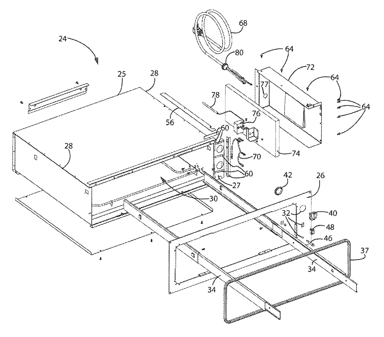
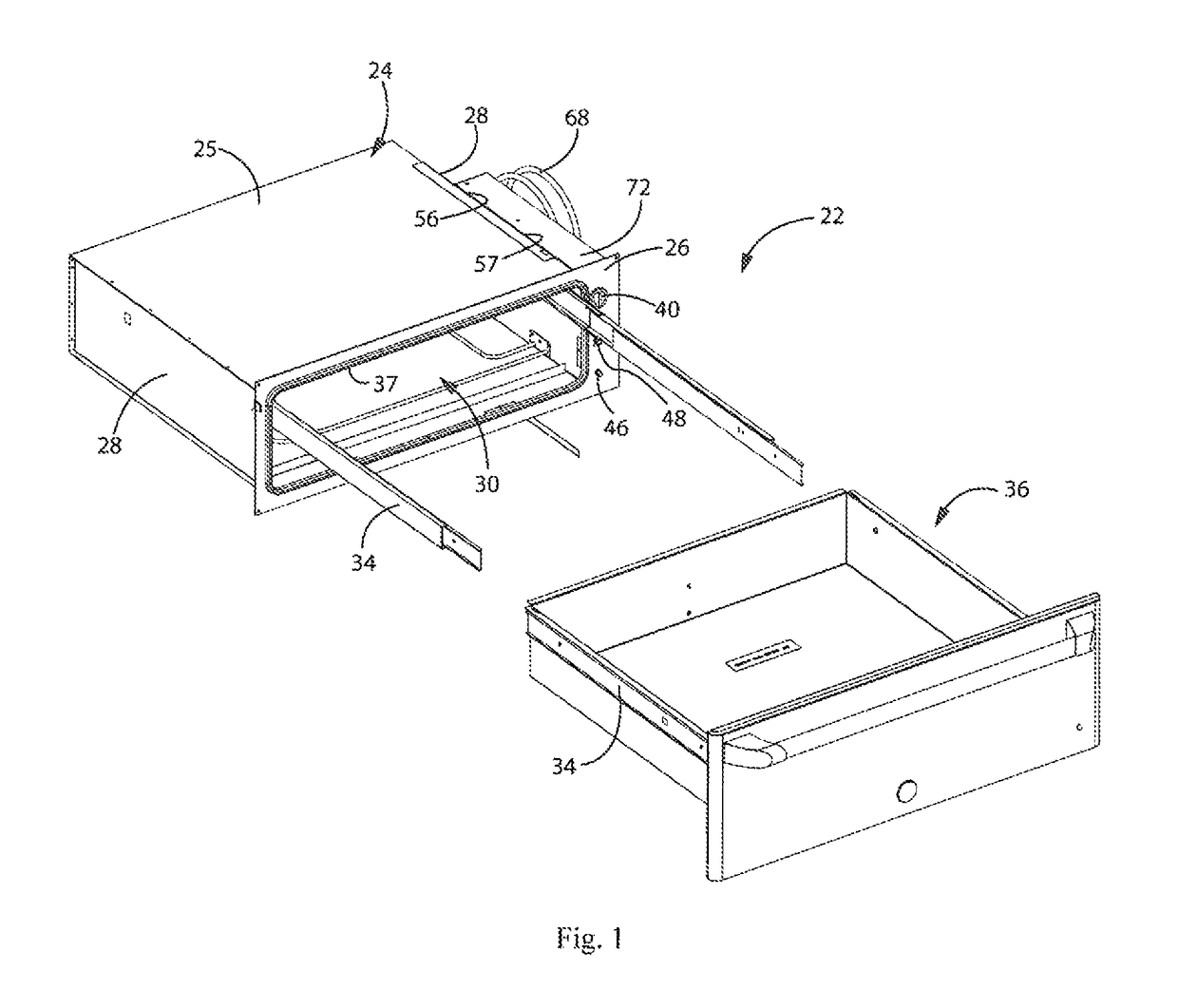
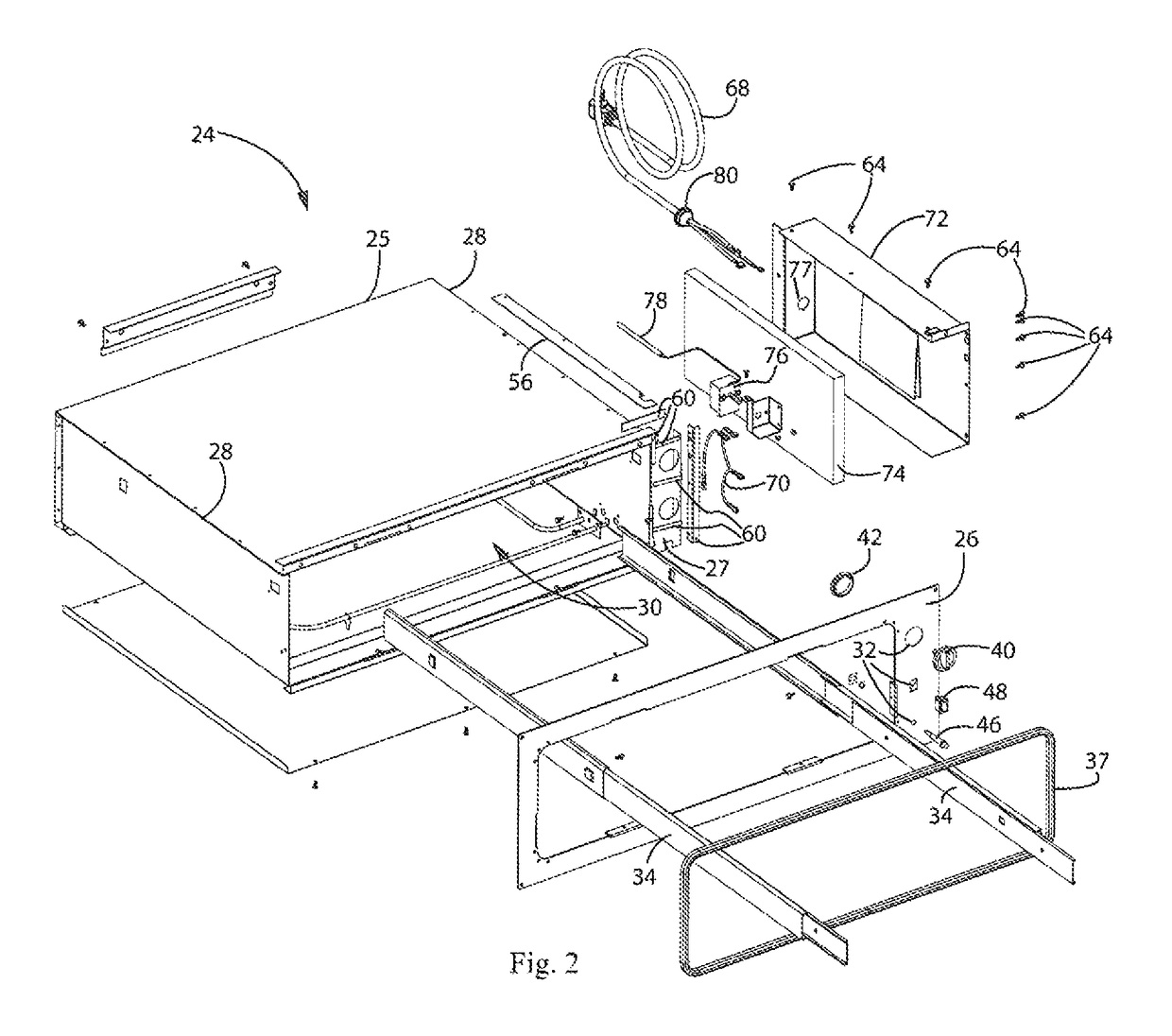
[0035]Beginning with FIG. 1, an appliance 22 is shown in a partially exploded, perspective view. The appliance 22 includes a chassis 24 and a drawer 36. The drawer 36 may be inserted into the chassis 24 and extended from the chassis 24 by gliding along a pair of rails 34. The chassis 24 is preferably formed in the shape of a box 25 with sides 28 and a front portion 26. A cavity 30 forms the interior of the box 25 and receives the drawer 36. A gasket 37 may be used to seal the cavity 30 when the drawer 36 is in the retracted position and inside the cavity.

[0036]In order to control the function of the appliance 22, a plurality of manual controls is included on the front portion 26 of the chassis 24. The manual controls may include a touch screen LCD, pushbuttons, capacitive touch bu...


PUM

PropertyMeasurementUnit
flexibleaaaaaaaaaa
inclined angleaaaaaaaaaa
forceaaaaaaaaaa

Abstract

A spill-resistant appliance may be constructed to prevent spilled liquids from entering a control housing and contacting electronics with the use of a first sealant preferably formed out of santoprene and a second sealant preferably formed out of a very high bond, double-sided foam tape. The first sealant and the second sealant may be used in various areas of the control housing that contains electronics for operating the appliance. The first and second sealants may also be used to help attach the control housing to other components of the appliance.

Description

CROSS-REFERENCE TO RELATED APPLICATION[0001]This application claims priority from U.S. Provisional Patent Application Ser. No. 61 / 755,144, filed on Jan. 22, 2013, the entirety of which is expressly incorporated by reference herein.BACKGROUND OF THE INVENTION[0002]1. Field of the Invention[0003]Spill protection is often sought for appliances used in both the kitchen and outdoors. This invention relates to preventing liquids from entering the internals of such appliances.[0004]2. Discussion of the Related Art[0005]Warming drawers are well known in the prior art. U.S. Patent No. D608,144 discloses a warming drawer wherein the controls are exposed on the drawer front. During use, it is possible for liquid spills above the drawer to drip onto the controls and potentially interfere with proper operation.[0006]Another example of a warming drawer is disclosed in U.S. Pat. No. 6,849,835. As shown in FIG. 1, control knobs are exposed on an outer surface of the housing. Just as described above...

Claims


Application Information

Patent Timeline
Patent Type & Authority Patents(United States)
IPC IPC(8): H05B1/02F24C15/00A47J39/00B23P19/00A47J36/24
CPCB23P19/00A47J36/2483Y10T29/49982Y10T29/49826
Inventor JONOVIC, SCOTT A.PUNZEL, WILLIAM H.FREDRICK, ROBERT E.
Owner HAIER US APPLIANCE SOLUTIONS INC D B A GE APPLIANCES
Why Eureka
Try Eureka