
Pulley for alternator

a technology for pulling a pulley and an alternator, which is applied in the direction of gearing, couplings, hoisting equipment, etc., can solve the problems of significant waveform changes, inability to stabilize, and tight belt wounding on the pulley, so as to effectively mitigate the vibration or belt slack or damage of the pulley, improving the overall operating efficiency and service life of the alternator

Active Publication Date: 2016-12-27
VICTORY IND CORP
View PDF58 Cites 3 Cited by
  • Summary
  • Abstract
  • Description
  • Claims
  • Application Information

AI Technical Summary

Benefits of technology

[0006]In view of the deficiency of the prior art, the inventor proposes a pulley for an alternator which can effectively mitigate the vibration or belt slack or damage of the pulley caused by the speed change, thereby improving the overall operating efficiency and service life of the alternator.
[0018]According to another implementation of the exemplary embodiment, an inner circumferential wall surface of the outer wheel is provided with a step portion, for the clutch wheel to abut against, thereby limiting an axial displacement of the clutch wheel.
[0021]According to another implementation of the first exemplary embodiment, when the wire profile of the torque spring is rectangular, two end surfaces of the torque spring are grinded, so as to enhance axial positioning of the torque spring and control a free length of the torque spring more precisely.
[0022]According to another implementation of the exemplary embodiment, two sides of the clutch wheel are each provided with an oil seal element, so as to prevent liquid in the clutch wheel from flowing into the outer wheel.
[0025]According to another implementation of the exemplary embodiment, an end, corresponding to the second end of the hollow core shaft, of the outer wheel is arranged with a dust cover, so as to prevent external dust from entering the outer wheel.

Problems solved by technology

However, in conventional alternator design, when an engine starts, or accelerates or decelerates quickly in an instant, a waveform changes significantly at the moment the generator charges a battery, and it cannot be stabilized.
In addition, one side of the belt wound on the pulley is tight, and the other side thereof is slack.
However, when a rotation speed at which the engine transmits power changes suddenly, because the pulley of the generator is locked by a nut and the belt is made of a flexible material and cannot reflect the rotation speed immediately, a slip is easily caused between the belt and the pulley.
The value of the centrifugal force changes with the rotation speed, and therefore the belt is often affected by adverse factors of an internal micro tension, which pulls the belt, and external large-amplitude shaking.

Method used


Image

  • Pulley for alternator
  • Pulley for alternator
  • Pulley for alternator

Examples


Embodiment Construction

[0071]The following describes the present invention in the context of the exemplary embodiment described above. The skilled person will appreciate that the following description is used to describe the present invention and illustrate the advantages thereof, but it does not mean that the present invention is limited to such an embodiment, and in particular, the scope of the present invention includes equivalents thereof.

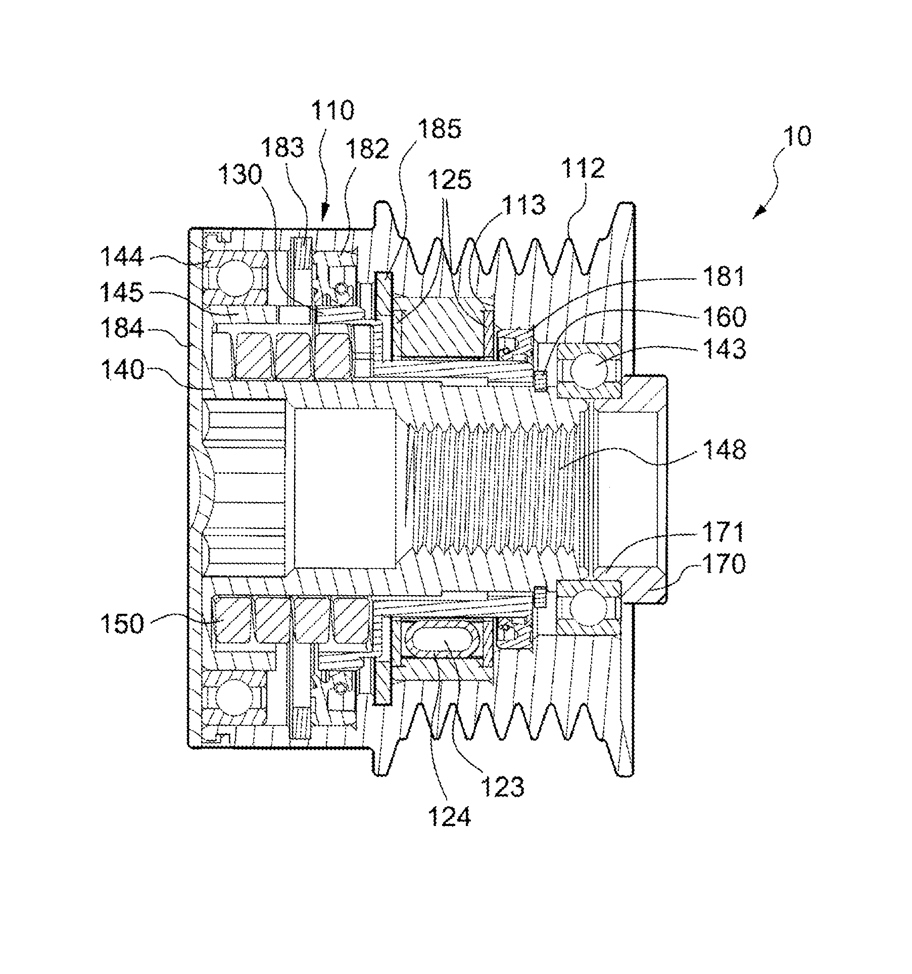
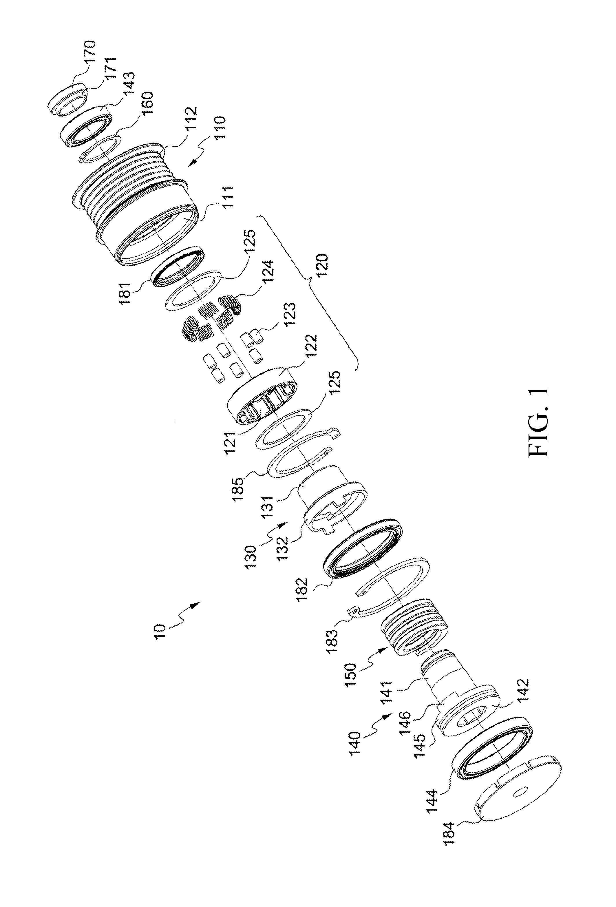
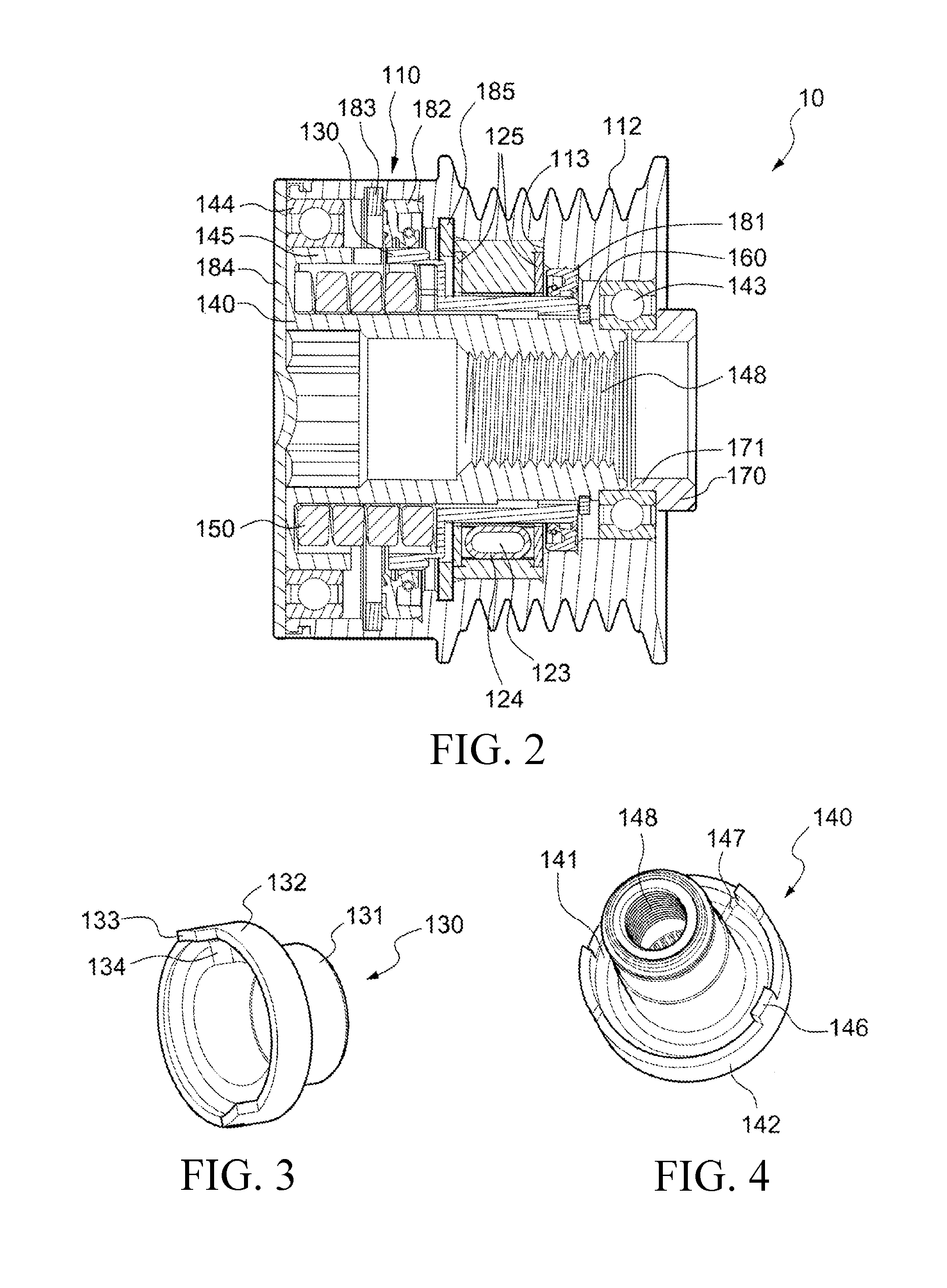
[0072]FIG. 1 and FIG. 2 are respectively a three-dimensional exploded view and a sectional assembled view of a pulley for an alternator according to the present invention. As shown in FIG. 1 and FIG. 2, a pulley 10 for an alternator according to the present invention mainly includes an outer wheel 110, a clutch wheel 120, a hollow connecting shaft 130, a hollow core shaft 140, an elastic element 150, and a tight-fit component 160. The outer wheel 110 is a wheel-shaped member provided with an axle hole 111 at the center, and is provided with a belt groove 112 on an ou...


PUM


Abstract

The present invention relates to a pulley for an alternator, and in particular, to a pulley applicable to an automotive alternator. The pulley effectively mitigates the problem that a belt and a tension pulley of an alternator vibrate because a rotation speed of a vehicle engine changes, thereby improving the overall operating efficiency of the alternator and the service life of the working belt and the tension pulley.

Description

CROSS REFERENCE TO RELATED APPLICATIONS[0001]This application claims the benefit of priority from Taiwan patent application TW 103 124 193, filed Jul. 14, 2014, the contents of which are herein incorporated by reference.BACKGROUND OF THE INVENTION[0002]The present invention relates to a pulley for an alternator, and in particular, to a pulley for an automotive alternator.[0003]An alternator is a type of generator that can produce an alternating current by converting mechanical energy into electrical energy. An automotive alternator converts mechanical energy of an engine into electrical energy to charge a battery, so as to supply electrical power to other electrical appliances on the automobile, and start a motor to rotate the engine.[0004]An alternator generally has an annular stator and a rotor received in the annular stator. A wire is wound on the stator, and the rotor rotates rapidly in the stator so that the wire moves relative to a magnetic field generated by the rotor, and an...

Claims


Application Information

Patent Timeline
Patent Type & Authority Patents(United States)
IPC IPC(8): F16H9/00F16H63/00F16H61/00F16H59/00F16D3/00F02B67/06F16H55/14F16H55/36
CPCF16H55/36F02B67/06F16H2055/366
Inventor CHANG, HUNG-CHIHLIU, SZU-EN
Owner VICTORY IND CORP
Learn More