Brake system for vehicles

a technology for brake systems and vehicles, applied in braking systems, transportation and packaging, braking components, etc., can solve the problems of not being able to switch off the brake system, the brake system is less suitable for motor vehicles, etc., and achieve the effect of high-automatic driving or independent driving

Active Publication Date: 2018-09-04
CONTINENTAL TEVES AG & CO OHG
View PDF28 Cites 2 Cited by
  • Summary
  • Abstract
  • Description
  • Claims
  • Application Information

AI Technical Summary

Benefits of technology

[0009]An aspect of the invention affords the advantage that, with any single error of the brake system, safe braking of the vehicle in any driving situations, that is to say, in particular with wheel-specific wheel brake pressures, continues to be possible, without the support of the driver being necessary for this.
[0010]An aspect of the invention further affords the advantage that there is provided a brake system which ensures a redundant wheel-individual brake control function, in particular an ESP function (ESP: Electronic Stability Program).
[0011]The brake system according to an aspect of the invention further affords the advantage that it can optionally be supplemented in a vehicle or in a brake system known per se in order to enable highly automated driving or independent driving.

Problems solved by technology

Such a brake system is therefore less suitable for motor vehicles which are driven in a highly automated or independent manner.
For highly automatic or highly automated driving (HAD), it is not possible to switch off the brake system after any initial error.

Method used


Image

  • Brake system for vehicles
  • Brake system for vehicles
  • Brake system for vehicles

Examples


Embodiment Construction

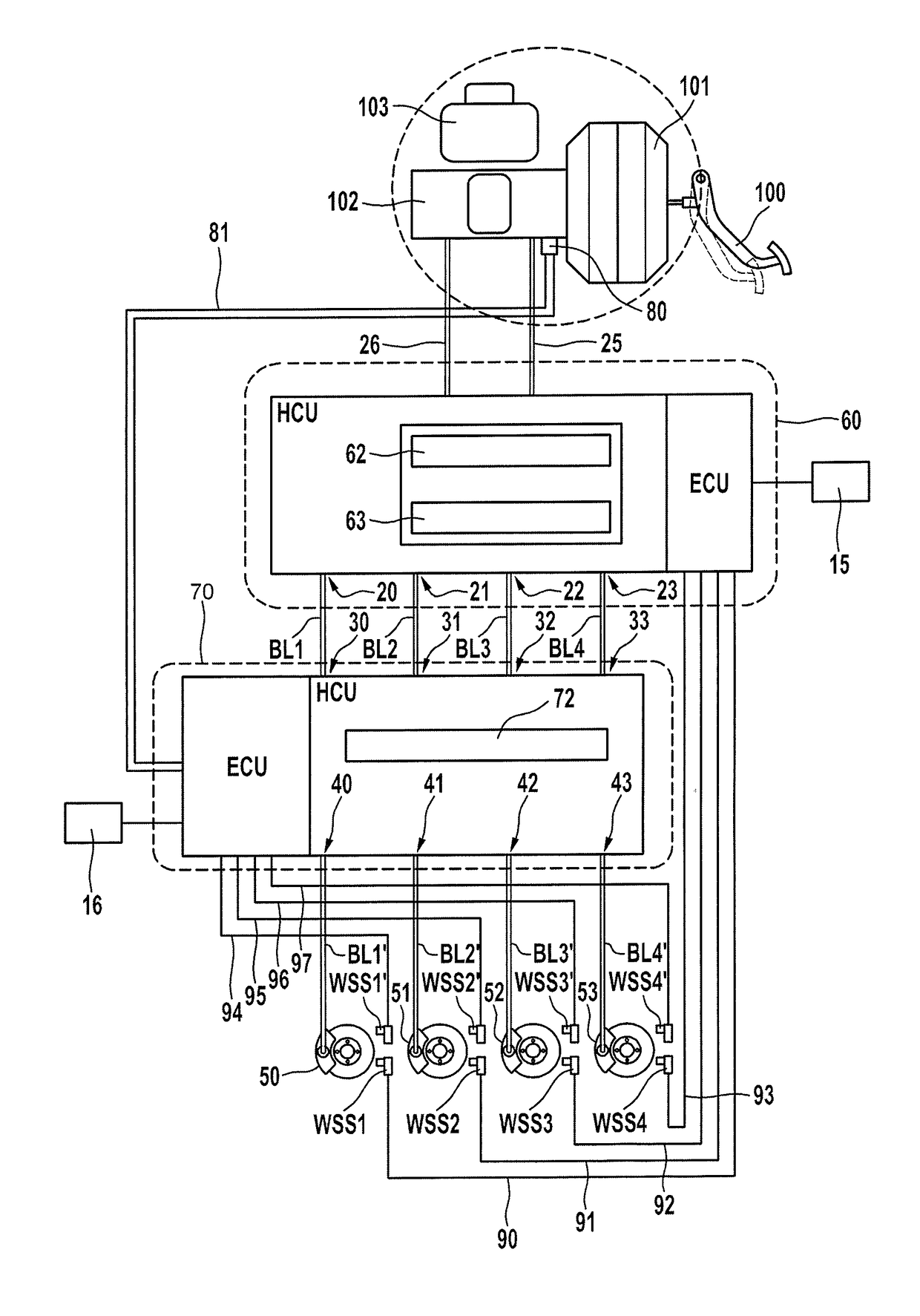
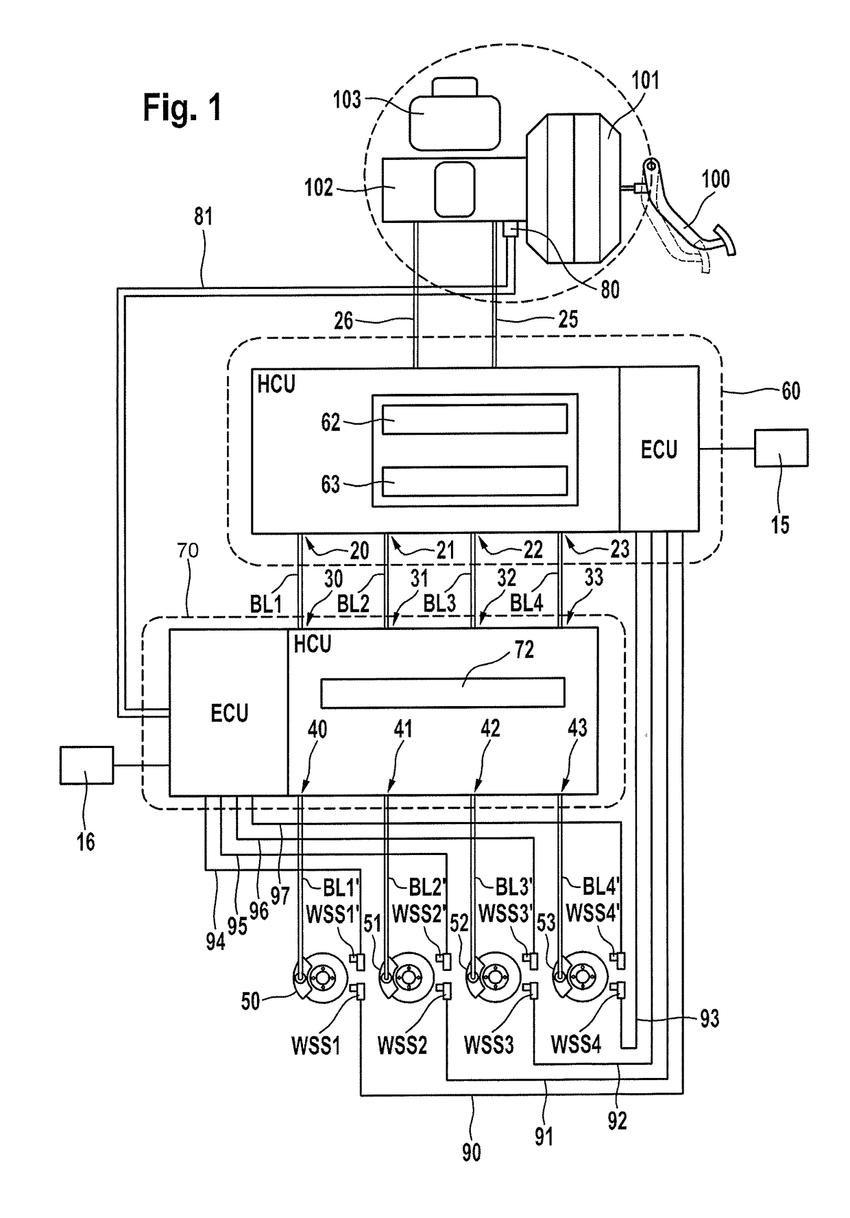
[0042]FIG. 1 is a schematic illustration of an embodiment of a brake system according to an aspect of the invention. The exemplary brake system comprises a brake pedal 100, a main brake cylinder (tandem main brake cylinder) 102 with associated pressure medium storage container 103, an (active) electrically controllable vacuum brake booster 101 which is arranged upstream of the main brake cylinder, a first electrohydraulic brake control device 60, a second electrohydraulic brake control device 70 and four hydraulic wheel brakes 50, 51, 52, 53.

[0043]The two pressure chambers of the tandem main brake cylinder 102 are connected by means of brake circuit lines 25, 26 to the two input pressure connections of the brake control device 60. The first brake control device 60 has wheel-specific output pressure connections 20, 21, 22, 23 and the second brake control device 70 has wheel-specific input pressure connections 30, 31, 32, 33. Each output pressure connection 20, 21, 22, 23 is connected...


PUM


Abstract

A brake system for vehicles, in particular motor vehicles, including a master brake cylinder, in particular a tandem master brake cylinder, a brake booster which is connected upstream of the master brake cylinder, in particular at least four hydraulically actuatable wheel brakes, and a first electrohydraulic brake control device which includes a first pressure regulating valve arrangement for adjusting wheel-specific brake pressures, in particular an electrically actuatable pressure source, and a wheel-specific outlet pressure connection for each wheel brake, wherein the brake booster is designed to be electrically actuatable, and a second electrohydraulic brake control device is provided which includes a second pressure regulating valve arrangement, in particular for adjusting wheel-specific brake pressures, and which is connected in series between the first brake control device and the wheel brakes.

Description

CROSS REFERENCE TO RELATED APPLICATIONS[0001]This application is the U.S. National Phase Application of PCT International Application No. PCT / EP2014 / 077872, filed Dec. 16, 2014, which claims priority to German Patent Application No. 10 2014 200 662.7, filed Jan. 16, 2014 and German Patent Application No. 10 2014 220 441.0, filed Oct. 9, 2014, the contents of such applications being incorporated by reference herein.FIELD OF THE INVENTION[0002]The invention relates to a brake system for vehicles.BACKGROUND OF THE INVENTION[0003]Electrohydraulic brake systems are widespread in motor vehicles. Brake systems are known, for example, from DE 10 2010 062 387 A1, which is incorporated by reference, and comprise a main brake cylinder, a vacuum brake booster which is arranged upstream of the main brake cylinder and an electrohydraulic ABS / ESP brake control device, wherein the brake control device comprises pressure control valves and an electrically controllable pump for adjusting wheel-specif...

Claims


Application Information

Patent Timeline
Patent Type & Authority Patents(United States)
IPC IPC(8): B60T8/34B60T7/12B60T8/48B60T7/04B60T13/14B60T13/66B60T8/92B60T17/18
CPCB60T7/12B60T7/042B60T8/348B60T8/4854B60T8/92B60T13/146B60T13/662B60T8/4872B60T2270/413B60T17/18
Inventor LINHOFF, PAULECKERT, ALFRED
Owner CONTINENTAL TEVES AG & CO OHG
Why Eureka
Try Eureka