Eureka AIR delivers breakthrough ideas for toughest innovation challenges, trusted by R&D personnel around the world.

Brake-aiding device

a technology of brakes and braking devices, applied in the field of transmission, can solve the problems of vehicle rolling over due to inertia, prone to skid and even rollover, and inability to stop, so as to achieve safe braking and prevent accidents

Active Publication Date: 2016-11-15
ANSURE
View PDF5 Cites 2 Cited by
  • Summary
  • Abstract
  • Description
  • Claims
  • Application Information

AI Technical Summary

Benefits of technology

The present invention is a brake-aiding device that uses linked revolvers to brake both of a two-wheeled vehicle's front and rear wheels. The device ensures safe braking and prevents accidents by braking the rear wheel first and then the front wheel. It also maintains the braking force generated at the rear wheel greater than that generated at the front wheel by design. The device is compact, light, and easy to install due to its three-dimensional structure and linked revolvers. The use of the device integrates well with existing brake systems, resulting in smoother, stable, and durable operation of the cables.

Problems solved by technology

In the event that braking is applied improperly, skid and even rollover tend to happen.
In this case, if the rear wheel is locked by the brake, and the friction developed between the tire and the ground is insufficient to stop the vehicle, skid or shift can happen.
On the other hand, if it is the front wheel that gets stuck, the vehicle can roll over due to inertia.
However, these devices are bulky and heavy, making them unfavorable to the appearance and structural balance of the bicycles having them and come against the trend toward light-weight bicycles.

Method used


Image

  • Brake-aiding device
  • Brake-aiding device
  • Brake-aiding device

Examples


first embodiment

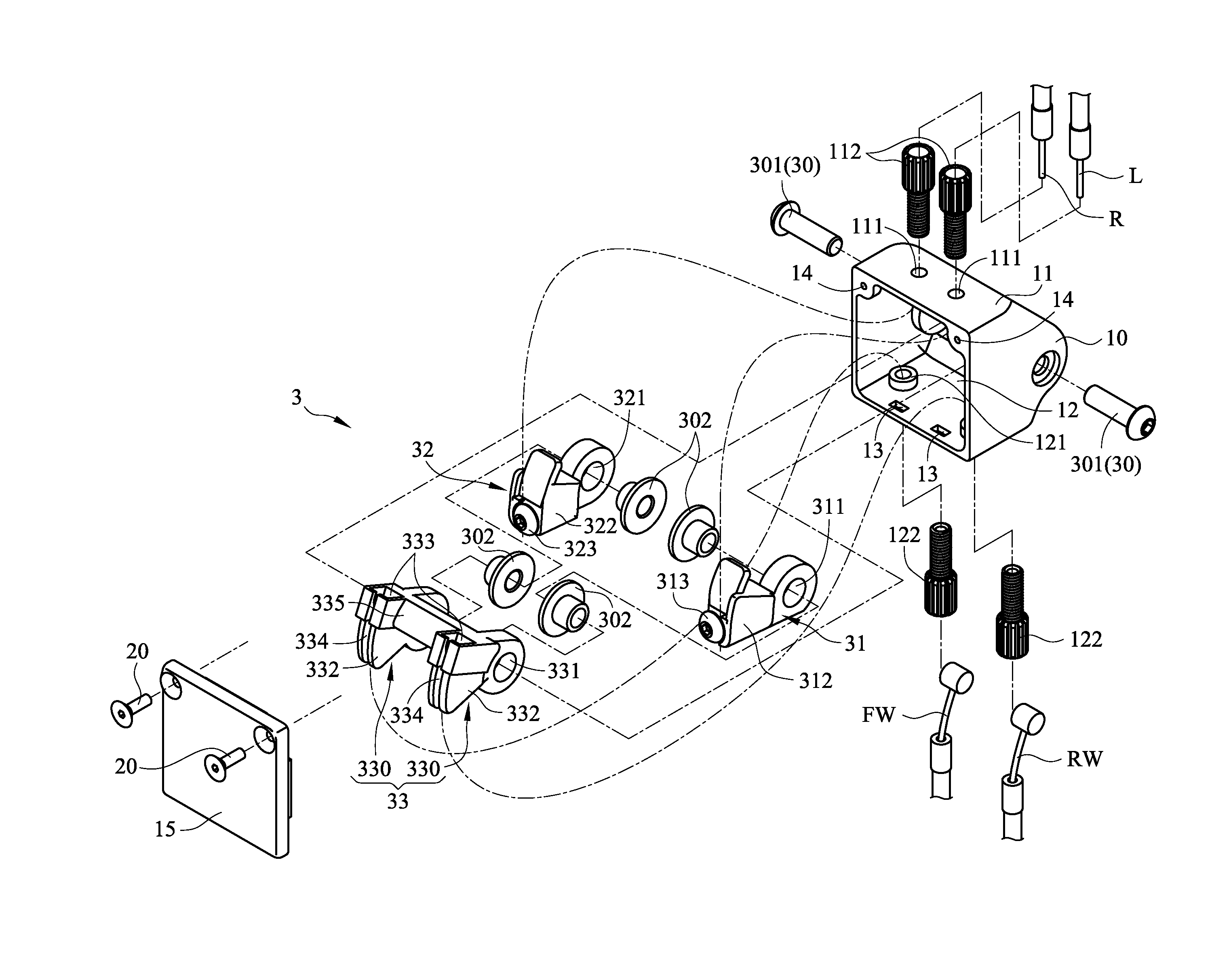
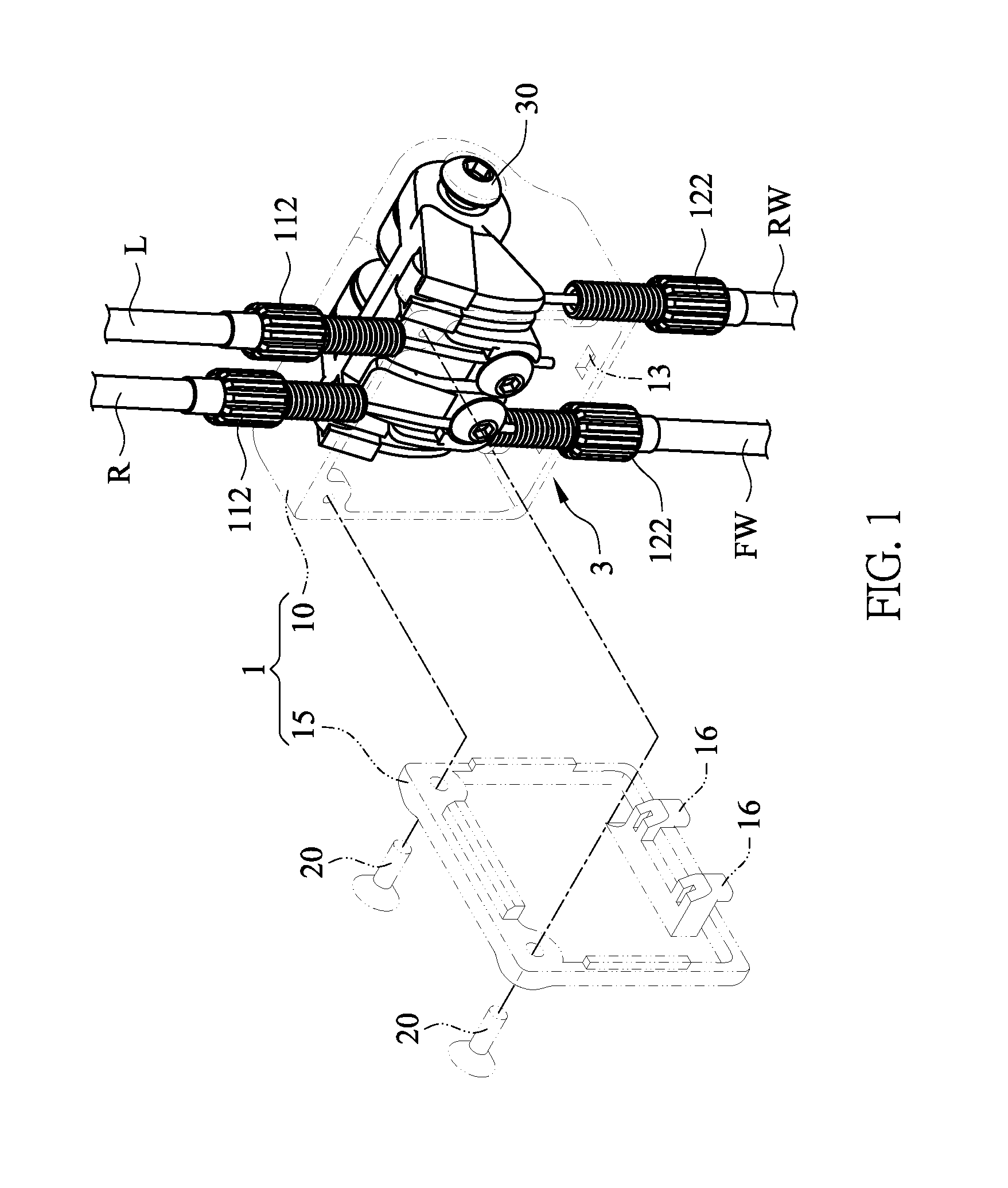
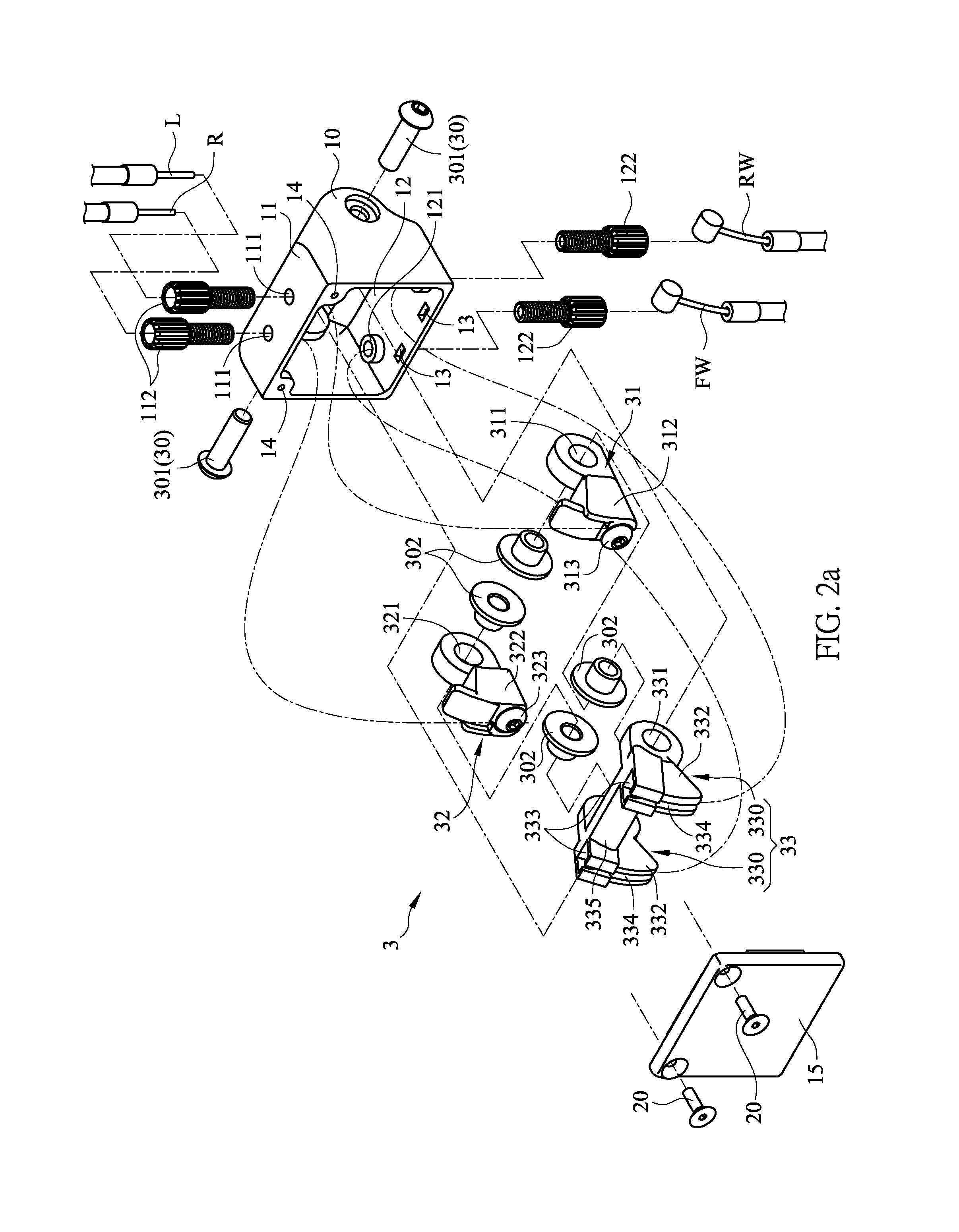
[0032]Referring to FIG. 1 and FIG. 2a, in the present invention, a brake-aiding device primarily comprises a hollow casing 1 and a drive mechanism 3 installed therein.

[0033]The casing 1 is mainly composed of a casing body10 and a front cover 15. The casing body 10 is of a three-dimensional hollow structure that has a forward-facing opening and a front cover 15 covering the opening. When the front cover 15 combined with the casing body 10, the opening is closed. The casing body 10 comprises mortise 13 formed at its bottom 12 near the opening for fittingly receiving and thus positioning tenons 16 corresponding formed on the front cover 15. Fixing holes 14 are provided on the casing body 10 above the opening so that fixing members 20 can be screws thereinto to fix the front cover 15 to the casing body 10, thereby forming the closed casing 1. The casing body 10 has a top 11 and the bottom 12, each of which is provided with two through holes 111 or 121. In the through holes 111, 121, gui...

second embodiment

[0045]FIG. 7a and FIG. 7b depict the brake-aiding device of the present invention that is not activated. At this time the first revolver 41 and the second revolver 42 are pushed by the driven revolver 43 and abut against the bottom 12 of the casing body 10. When the rider wants to brake, as shown in FIG. 8a and FIG. 8b, by pressing the right brake lever, the right brake cable R is pulled and rotates upward to drive the second revolver 42 connected therewith to rotate upward. Then since the second revolver 42 abuts against the propping portion 435 of the driven revolver 43, the driven revolver 43 is driven to rotate with the second revolver 42, and pulls the front- and rear-wheel brake cables FW, RW to move upward, thereby braking the front and rear wheels. On the other hand, if the rider presses the left brake lever, as shown in FIG. 9a and FIG. 9b, the left brake cable L is pulled to move upward and drives the first revolver 41 connected therewith to rotate upward. Then since the f...


PUM


Abstract

A brake-aiding device includes a casing and a drive mechanism installed in the casing. The drive mechanism has a revolving axle, and first revolver, a second revolver and a driven revolver that rotate against the revolving axle. The driven revolver has at least one propping portion for providing unidirectional stop to the first revolver and the second revolver. When brake lever cables of a two-wheeled vehicle are connected to the first and second revolver, and front- and rear-wheel brake cables of the vehicle are connected to the driven revolver, by operating either of the vehicle's left and right brake levers, both of the vehicle's front and rear wheels are braked. During the braking, the rear wheel is brakes before the front wheel is brakes, and a braking force at the rear wheel keeps greater than a braking force at the front wheel braking force.

Description

BACKGROUND OF THE INVENTION[0001]1. Technical Field[0002]The present invention relates to transmissions used in brakes of two-wheeled vehicles, and more particularly to a brake-aiding device that is capable of applying synchronously front- and rear-wheel brakes and controlling brake strength.[0003]2. Description of Related Art[0004]Pull-out handbrake systems are widely seen in general two-wheel vehicles, such as bicycles, motorcycles, and electric motorcycles. Such a system includes two brake levers attached to the bike's left and right handles, respectively. The brake levers are connected to the bike's front-wheel brake and rear-wheel brake respectively through brake cables so that braking the bike's front and rear wheels can be achieved by pulling the brake levers. It is to be noted that braking, which brings about deceleration, is realized when friction is developed between the wheel tires and the ground. During advance of a two-wheel vehicle (such as a bicycle or any of various ...

Claims


Application Information

Patent Timeline
Patent Type & Authority Patents(United States)
IPC IPC(8): B62L3/08B60T11/06B60T11/04B60T7/10
CPCB60T11/06B60T11/046B60T7/102B62L3/08B60T8/261
Inventor TSENG, TON-RONG
Owner ANSURE
Why Eureka
Eureka Blog
Learn More