Brake system for vehicles
- Summary
- Abstract
- Description
- Claims
- Application Information
AI Technical Summary
Benefits of technology
Problems solved by technology
Method used
Image
Examples
Embodiment Construction
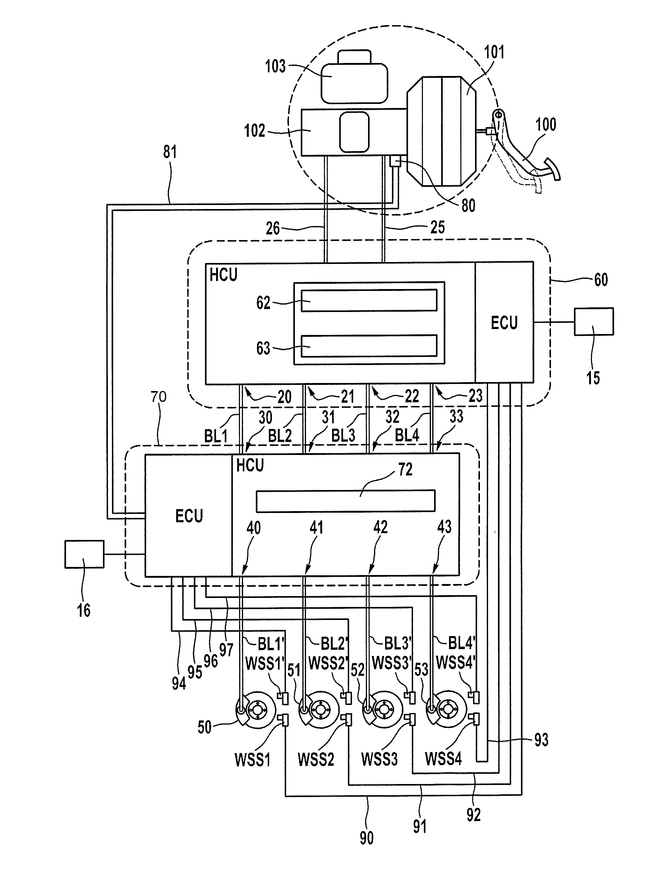
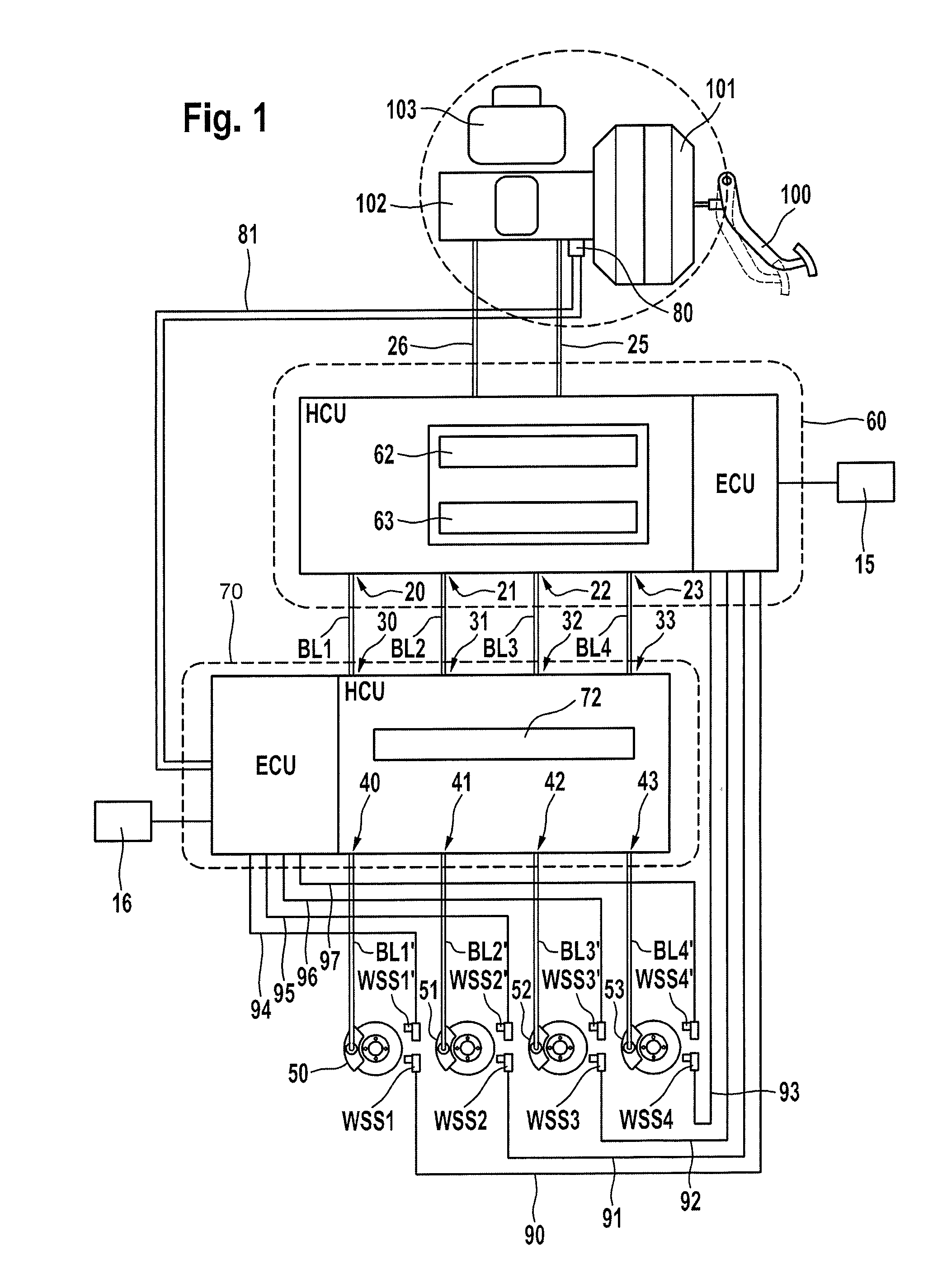
[0042]FIG. 1 is a schematic illustration of an embodiment of a brake system according to an aspect of the invention. The exemplary brake system comprises a brake pedal 100, a main brake cylinder (tandem main brake cylinder) 102 with associated pressure medium storage container 103, an (active) electrically controllable vacuum brake booster 101 which is arranged upstream of the main brake cylinder, a first electrohydraulic brake control device 60, a second electrohydraulic brake control device 70 and four hydraulic wheel brakes 50, 51, 52, 53.
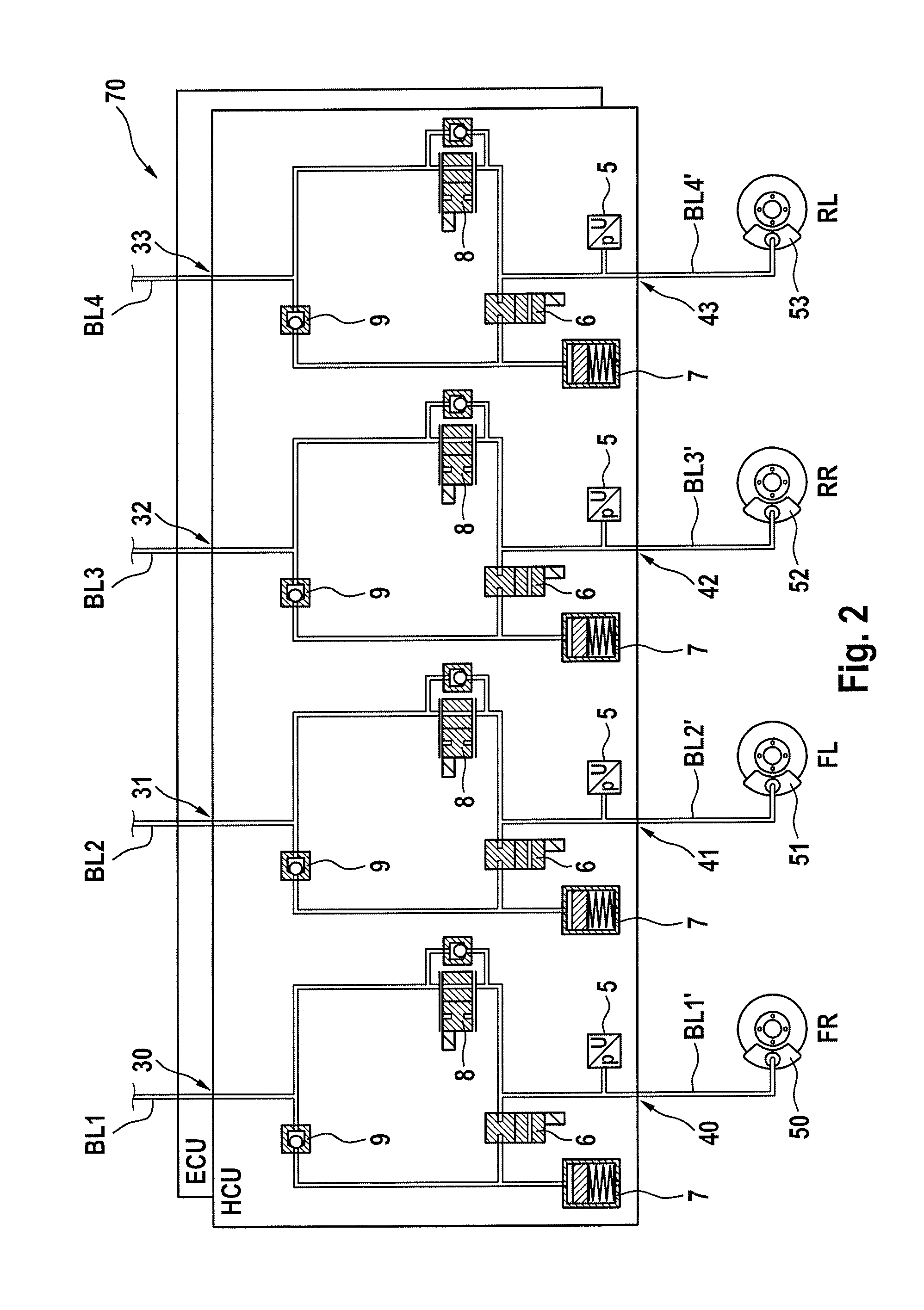
[0043]The two pressure chambers of the tandem main brake cylinder 102 are connected by means of brake circuit lines 25, 26 to the two input pressure connections of the brake control device 60. The first brake control device 60 has wheel-specific output pressure connections 20, 21, 22, 23 and the second brake control device 70 has wheel-specific input pressure connections 30, 31, 32, 33. Each output pressure connection 20, 21, 22, 23 is connected...
PUM
 Abstract
Description
Claims
Application Information
 - R&D
- Intellectual Property
- Life Sciences
- Materials
- Tech Scout
- Unparalleled Data Quality
- Higher Quality Content
- 60% Fewer Hallucinations
Browse by: Latest US Patents, China's latest patents, Technical Efficacy Thesaurus, Application Domain, Technology Topic, Popular Technical Reports.
© 2025 PatSnap. All rights reserved.Legal|Privacy policy|Modern Slavery Act Transparency Statement|Sitemap|About US| Contact US: help@patsnap.com


