Air hood

a technology of air ducts and hoods, which is applied in the field of air ducts, can solve the problems of large outside dimensions, large surface area of refrigeration devices, and large size of refrigeration devices having such prior art assemblies

Active Publication Date: 2018-09-18
COLMAC COIL MFG
View PDF10 Cites 94 Cited by
  • Summary
  • Abstract
  • Description
  • Claims
  • Application Information

AI Technical Summary

Benefits of technology

[0005]Still another aspect of the present invention relates to an air hood which includes a main body which is attached to a refrigeration device having an air intake side, and wherein the refrigeration device has a refrigeration coil or fins, which are positioned adjacent to the air intake side, and which further periodically require defrosting by undergoing a defrost cycle which generates heat, and wherein the main body of the air hood is reconfigurable, and moveable from a first, collapsed position, and wherein the main body is oriented so as to cover and substantially occlude the air intake side of the refrigeration device so as to reduce an operational size of the refrigeration device, and minimize freight expenses for shipping an operational refrigeration device to an installation site, and which further protects the refrigeration coil or fins during shipment and installation, and wherein the main body, when moved to a second position, forms a rigid operational air hood structure, and which extends laterally, outwardly relative to the refrigeration device, and which further defines a hood opening that allows access to the air intake side of the refrigeration device, and wherein the hood opening has a predetermined cross-sectional dimension, and wherein the main body, when located in the second position, captures, at least in part, a portion of the heat generated during a defrost cycle, and further reduces a duration of the defrost cycle, and additionally increases the efficiency of the defrost cycle.

Problems solved by technology

Those skilled in the art will recognize that when cooling air to temperatures below freezing, the surfaces of a refrigeration device which may include refrigerant fins and tubes, unavoidably accumulate frost which then must be periodically removed during a defrosting cycle.
The defrosting cycle or process is inherently necessary, but some aspects of it is undesirable inasmuch as the defrosting cycle increases the overall refrigeration system power consumption by adding heat to the refrigerated space, and which subsequently must be removed by the refrigeration device or system after the defrosting cycle has been completed.
One of the detrimental features of employing such rigid, return air hoods is that such refrigeration devices having such prior art assemblies have larger, overall, outside dimensions.
These larger outside dimensions of the prior art refrigeration devices often significantly increases the shipping, and freight costs, and also further complicates and renders difficult the handling and rigging of the refrigeration devices when they arrive at their destination and are ready to be installed in their desired location.

Method used


Image

  • Air hood
  • Air hood
  • Air hood

Examples


Embodiment Construction

[0018]This disclosure of the invention is submitted in furtherance of the constitutional purposes of the U.S. Patent Laws “to promote the progress of science and useful arts” (Article 1, Section 8).

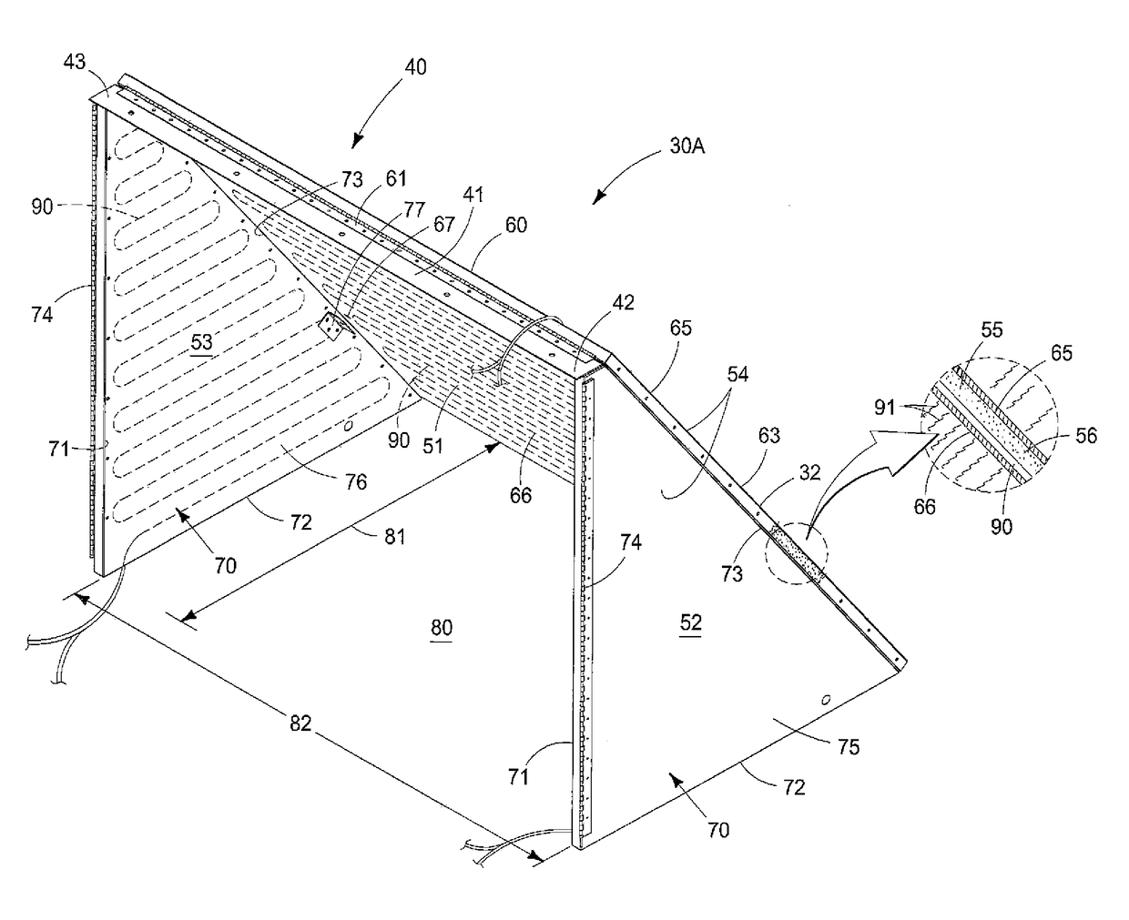
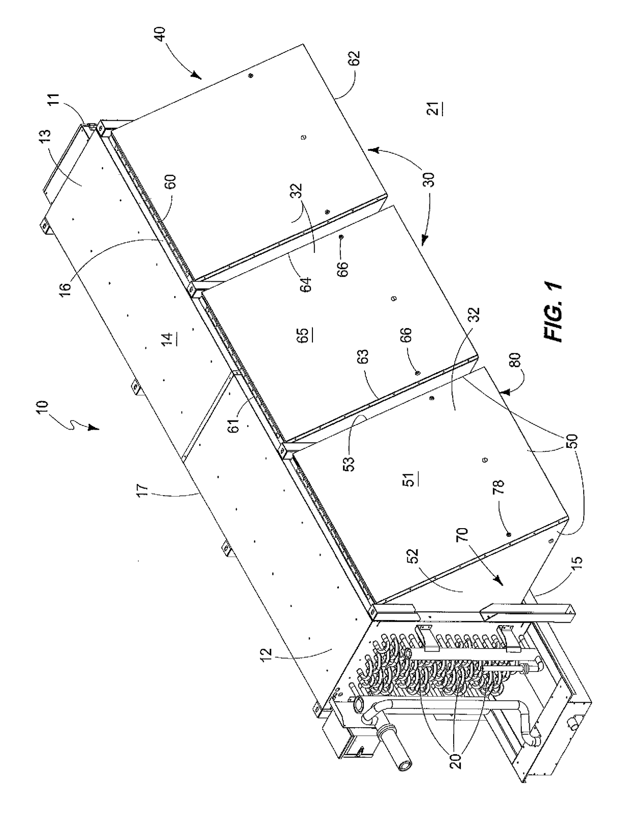
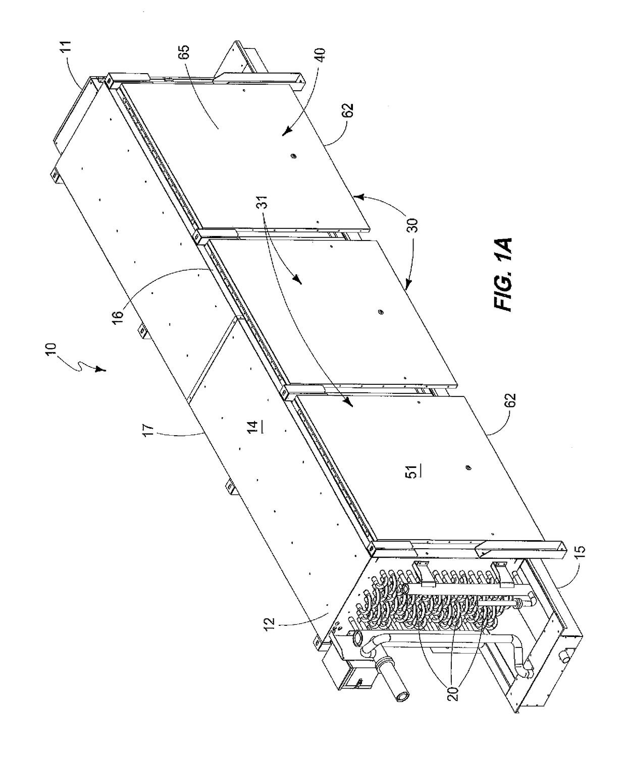
[0019]As noted earlier in this patent application, the present invention relates to an air hood (as later described), and which is useful when used on, and in combination with a refrigeration device 10 of conventional design. The refrigeration device 10 has a main body 11, with opposite first and second ends 12 and 13, respectively; a top surface 14, and an opposite bottom surface 15. Still further, the refrigeration device has a first, air intake side 16, and an opposite, second side 17. As best seen by reference to FIGS. 1 and 1A, respectively, the refrigeration device 10 has given outside dimensions which vary depending upon the orientation of the air hood as well as will be discussed, below.

[0020]The refrigeration device 10 of the present invention further encloses refrigeration fins ...


PUM


Abstract

An air hood is described and which is arranged so as to be mounted on a refrigeration device of conventional design; the air hood is moveable between a first position where the air hood is collapsed and is placed in juxtaposed, covering relation relative to an air intake side of the refrigeration device, and a second position where the air hood is placed into an operational position which places it laterally outwardly relative to the air intake side of the refrigeration device.

Description

TECHNICAL FIELD[0001]The present invention relates to an air hood for use with a refrigeration device, and more specifically to a reconfigurable air hood which is moveable between a first, collapsed position, to a second, operational position; and wherein the air hood, in the first position, facilitates the shipping and installation of the refrigeration device; and when the air hood is located in the second position, the air hood enhances the operation of the refrigeration device upon which it has been installed.BACKGROUND OF THE INVENTION[0002]Those skilled in the art will recognize that when cooling air to temperatures below freezing, the surfaces of a refrigeration device which may include refrigerant fins and tubes, unavoidably accumulate frost which then must be periodically removed during a defrosting cycle. The defrosting cycle or process is inherently necessary, but some aspects of it is undesirable inasmuch as the defrosting cycle increases the overall refrigeration system ...

Claims


Application Information

Patent Timeline
Patent Type & Authority Patents(United States)
IPC IPC(8): F25D21/06B60H1/00F24F1/0059F25D17/06F25D21/04F25D21/08F25D23/02
CPCF25D17/067F25D2400/32F25D21/04F24F1/0059F25D21/08F25D23/028B60H1/00514B60H1/00671F24F1/0014F24F1/0011
Inventor NELSON, BRUCE IANHAROLD, JOSEPH RAYWILLIAMS, ROGER BRUCE
Owner COLMAC COIL MFG
Why Eureka
Try Eureka