
Electrical terminal having a push surface

a technology of electric terminals and push plates, which is applied in the direction of electrical apparatus, coupling device connections, connections effected by permanent deformation, etc., can solve the problems of terminal assembler injuries, terminal insertion or mate difficulties of flag terminals with mating terminals, etc., and achieves the effect of convenient and effective ma

Active Publication Date: 2018-09-18
TYCO ELECTRONICS LOGISTICS AG (CH)
View PDF11 Cites 11 Cited by
  • Summary
  • Abstract
  • Description
  • Claims
  • Application Information

AI Technical Summary

Benefits of technology

The invention aims to create a terminal that can be easily and safely mated with another terminal without special tools or injury. It is designed to be easily inserted into a connector housing and has an ergonomically friendly surface for easy mating or insertion.

Problems solved by technology

While flag terminals are beneficial in various applications, the insertion of the flag terminals into housings or the mating of the flag terminals with mating terminals can be difficult.
The bearing surface on known flat terminals is small and difficult to access and may have sharp edges, making it difficult to insert the terminals into the connector housing or mate with the mating terminals.
This can cause injuries to the assemblers of the terminals and damage to the terminals and connectors if the insertion of the terminal position assurance device or of the connector housing is not done properly.

Method used


Image

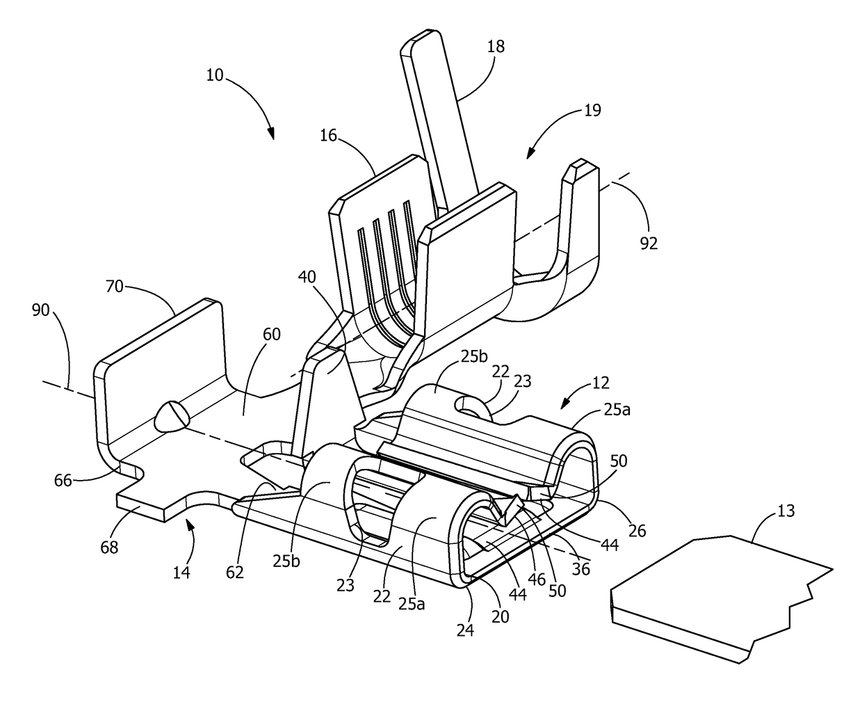
  • Electrical terminal having a push surface
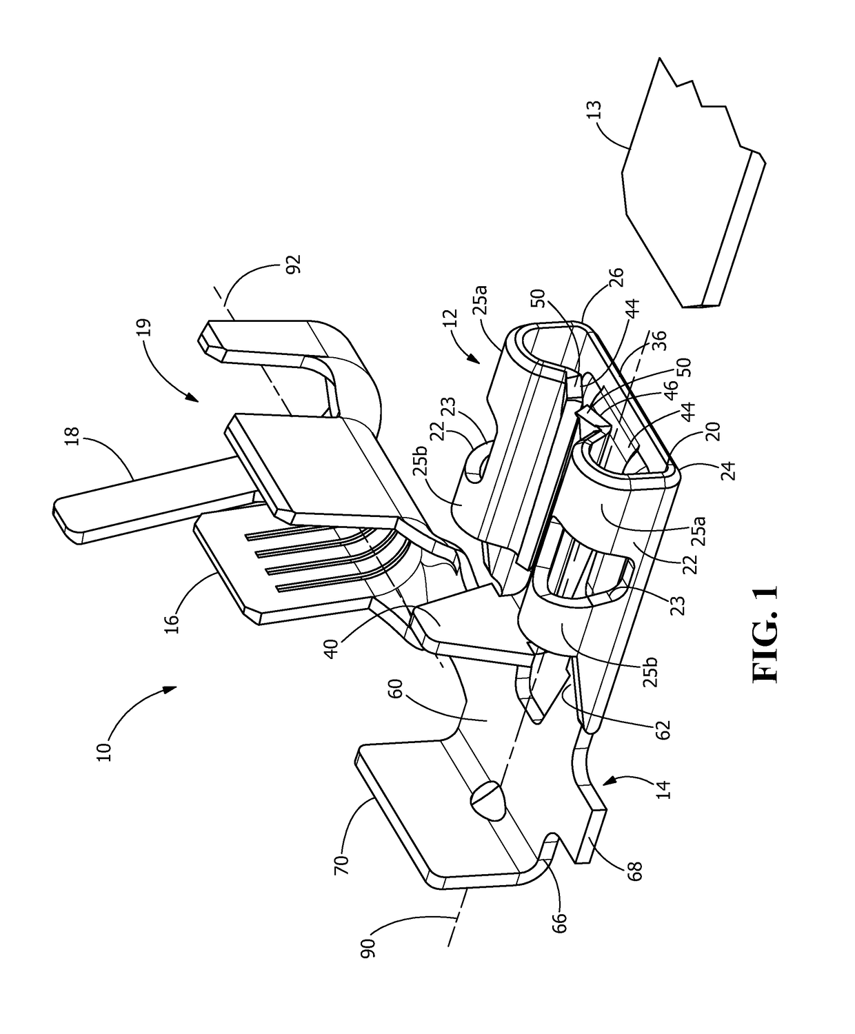
  • Electrical terminal having a push surface
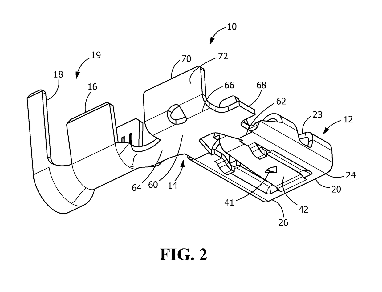
  • Electrical terminal having a push surface

Examples


Embodiment Construction

[0017]The description of illustrative embodiments according to principles of the present invention is intended to be read in connection with the accompanying drawings, which are to be considered part of the entire written description. In the description of embodiments of the invention disclosed herein, any reference to direction or orientation is merely intended for convenience of description and is not intended in any way to limit the scope of the present invention. Relative terms such as “lower,”“upper,”“horizontal,”“vertical,”“above,”“below,”“up,”“down,”“top” and “bottom” as well as derivative thereof (e.g., “horizontally,”“downwardly,”“upwardly,” etc.) should be construed to refer to the orientation as then described or as shown in the drawing under discussion. These relative terms are for convenience of description only and do not require that the apparatus be constructed or operated in a particular orientation unless explicitly indicated as such. Terms such as “attached,”“affi...


PUM


Abstract

An electrical terminal having a contact portion, a wire termination portion and a transition portion. The contact portion is configured to receive a mating terminal along a mating axis. The wire termination portion defines a wire termination axis that intersects the mating axis. The transition portion extends between the contact portion and the wire termination portion. The transition portion extends parallel to the mating axis and the wire termination axis. An engagement section extends at an angle from the transition portion. The engagement section has a push surface intersecting the mating axis. Wherein a force can be applied to the push surface to mate the contact portion with the mating terminal.

Description

FIELD OF THE INVENTION[0001]The present invention is directed to an electrical terminal with an enhanced bearing surface. In particular, the invention is directed to a terminal with a push surface which facilitates the mating or insertion of the terminal onto a mating connector or into a connector housing.BACKGROUND OF THE INVENTION[0002]Quick-connect terminal connectors are female terminals that mate with male tab terminals, tab adapters and tab terminal blocks. They are used where quick attachment and removability are desired. Flag terminals have the quick attachment at a right angle to the electrical wire to which the connector is attached. They are available as fully insulated, non-insulated or partially insulated. They are available with open or closed barrel crimps.[0003]One reason for the existence of flag terminals is for space saving because a right angle terminal can generally fit into smaller spaces than straight terminals. The quick connect portion of flag terminals of t...

Claims


Application Information

Patent Timeline
IPC IPC(8): H01R4/48H01R4/18
CPCH01R4/48H01R4/185H01R13/115
Inventor DIDONATO, MICHAEL EDWARDHUMPHREY, DAVID TRACYLANDON, III, RAYMOND L.
Owner TYCO ELECTRONICS LOGISTICS AG (CH)
Learn More