Endoscope having a sideways viewing direction

a technology of sideways and endoscopes, applied in the field of sideways viewing directions of endoscopes, can solve the problems of relatively complicated construction and involved, and achieve the effect of simple constructive measures

Active Publication Date: 2018-10-02
OLYMPUS WINTER & IBE
View PDF17 Cites 1 Cited by
  • Summary
  • Abstract
  • Description
  • Claims
  • Application Information

AI Technical Summary

Benefits of technology

[0011]Due to the fact that the pretensioning device is disposed in the distal region of the endoscope shaft at the axial bearing, the force impact occurs directly at the axial bearing and need not be transferred via the tubes sliding within one another. This leads to an axial bearing that is very efficient, continuously reliable, and free of play. The axial bearing no longer depends on the axially acting force being transferred via the inner tube, so that there are no frictional losses due to friction of the inner tube and outer tube, and also no longer any grabbing due to friction during rotation of the inner tube with respect to the outer tube. Furthermore, additional tubes for transferring axially acting forces can be omitted so that the placement according to the invention of the pretensioning device also leads to a simple and uncomplicated design.
[0016]The formation of the pretensioning device with magnets represents a particularly simple constructive measure.

Problems solved by technology

Because of this, the construction is relatively complicated and involved.

Method used


Image

  • Endoscope having a sideways viewing direction
  • Endoscope having a sideways viewing direction
  • Endoscope having a sideways viewing direction

Examples


Embodiment Construction

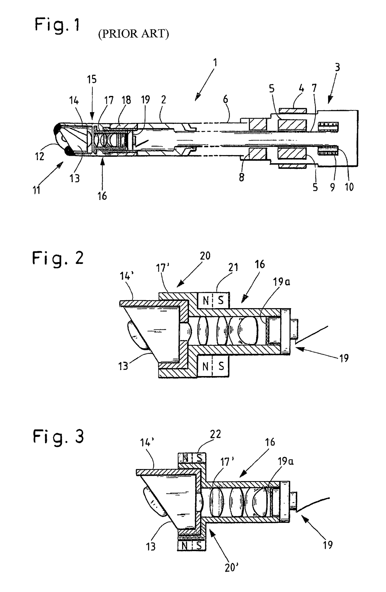
[0032]FIG. 1 schematically represents an endoscope 1 known from the prior art. The endoscope 1 at the proximal end, shown on the right side, has a handle 3 that ends in a shaft 2. The distal end of the shaft 2 is shown on the left side in FIG. 1.

[0033]The handle 3 has a rotary ring 4 by means of which, using bar magnets 5 that are connected to an inner tube 7, the inner tube 7 can be rotated with respect to an outer tube 6, in order to change the viewing direction of the endoscope 1. The inner tube 7 is mounted in the handle 3 additionally by means of a radial bearing 8. In addition, the handle 3 comprises a pretensioning device comprised of a compression spring 9, which is pretensioned with respect to a stop 10 for the compression spring 9. The compression spring 9 ensures that the inner tube 7 is pressed, or respectively pretensioned, in the axial direction toward the distal end 11 of the shaft 2.

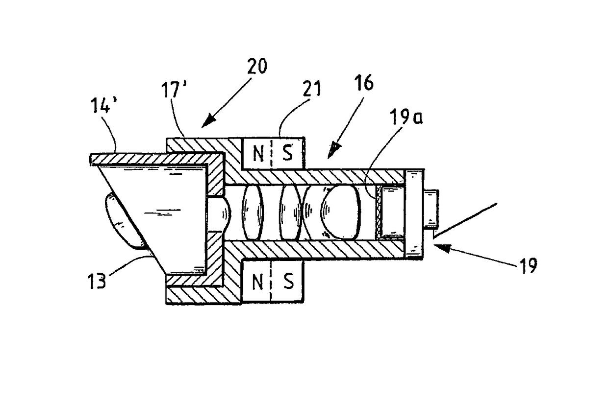
[0034]The shaft 2 at the distal end 11 has a window 12 that views sideways. Behind th...


PUM


Abstract

A sideways viewing endoscope including: a proximal handle, an endoscope shaft having outer and inner tubes, and first and second optical component assemblies arranged in a distal region of the endoscope shaft, the optical components assemblies can be rotated with respect to one another about a longitudinal axis of the endoscope shaft and are mounted against each other by an axial bearing that is disposed between the optical component assemblies and pretensioned by a pretensioning device; wherein the first optical component assembly is distally connected to the outer tube and comprises optical windows, prisms and / or lenses having a sideways viewing direction and the second optical component assembly is distally connected to the inner tube and comprises an image sensor having a straight-ahead viewing direction oriented in the direction of the longitudinal axis; and the pretensioning device is disposed in the distal region of the endoscope shaft at the axial bearing.

Description

CROSS-REFERENCE TO RELATED APPLICATION[0001]The present application is a continuation of PCT / EP2012 / 002791 filed on Jul. 3, 2012, which is based upon and claims the benefit to DE 10 2011 078 968.5 filed on Jul. 11, 2011, the entire contents of each of which are incorporated herein by reference.BACKGROUNDField[0002]The invention relates to an endoscope having a sideways viewing direction, comprising a proximal handle, an endoscope shaft having an outer tube and an inner tube, and two optical component assemblies which are arranged in the distal region of the endoscope shaft, can be rotated with respect to one another about the longitudinal axis of the endoscope shaft, and are mounted against each other by means of an axial bearing that is disposed between the optical component assemblies and is pretensioned by means of a pretensioning device, wherein a first optical component assembly that is distally connected to the outer tube comprises optical windows, prisms and / or lenses having ...

Claims


Application Information

Patent Timeline
Patent Type & Authority Patents(United States)
IPC IPC(8): A61B1/00A61B1/05
CPCA61B1/00177A61B1/00096A61B1/051A61B1/05A61B1/00179
Inventor WIETERS, MARTIN
Owner OLYMPUS WINTER & IBE
Why Eureka
Try Eureka