
Intervention Device with Electrodes

a technology of electrodes and electrodes, applied in the field of intervention devices, can solve the problems of difficult sizable neuromonitoring probes, unsuitable arrays, and ring-like electrodes used, and achieve the effect of facilitating the detection of potential nerve collisions

Inactive Publication Date: 2021-05-27
UNIVERSITY OF BERN +1
View PDF0 Cites 0 Cited by
  • Summary
  • Abstract
  • Description
  • Claims
  • Application Information

AI Technical Summary

Benefits of technology

The intervention device described in this patent has a multi-layered structure that creates multiple electrical field distributions around the substrate base. It also includes a processing unit that can evaluate the distance to a nerve based on an electric signal sent and / or perceived at the electrodes. This device optimizes the correlation of stimulation and muscle response to a prediction of nerve safety during intervention, providing a reliable and real-time assessment.

Problems solved by technology

Moreover, the discrete ring-like electrodes used in the disclosed neuromonitoring probe are not easily sizable along the elongated support structure and, as a consequence, are not suitable to create an array of spatially distinct surface electrodes, differently scaled to enable a wide variety of multiple electrical field distributions on the substrate body, or support structure, of a surgical tool.
Additionally, the discrete ring-like electrodes used in the neuromonitoring probe of the article are not best configured to redirect the signals corresponding to the detected stimulus response from the probe to a processing unit.
However, they are not structured in a way that the incorporated electrodes effectively enable multiple electrical field distributions for a multipolar characterization of electrical properties at an electrode-tissue (or electrode-cell) interface.
One of the main drawbacks of the stimulating drill bit of U.S. Pat. No. 8,326,414 B2 lies in that the electric field created at the point of the drill bit remains very narrow and localized, therefore not being very versatile or adaptable to a multiplicity of nerve detection situations.
There also exists a risk of short circuit, as a consequence of such structure.

Method used


Image

  • Intervention Device with Electrodes
  • Intervention Device with Electrodes
  • Intervention Device with Electrodes

Examples


Embodiment Construction

[0064]In the following description certain terms are used for reasons of convenience and are not intended to limit the invention. The terms “right”, “left”, “up”, “down”, “under” and “above” refer to directions in the figures. The terminology comprises the explicitly mentioned terms as well as their derivations and terms with a similar meaning. Also, spatially relative terms, such as “beneath”, “below”, “lower”, “above”, “upper”, “proximal”, “distal”, and the like, may be used to describe one element's or feature's relationship to another element or feature as illustrated in the figures. These spatially relative terms are intended to encompass different positions and orientations of the devices in use or operation in addition to the position and orientation shown in the figures. For example, if a device in the figures is turned over, elements described as “below” or “beneath” other elements or features would then be “above” or “over” the other elements or features. Thus, the exempla...


PUM


Abstract

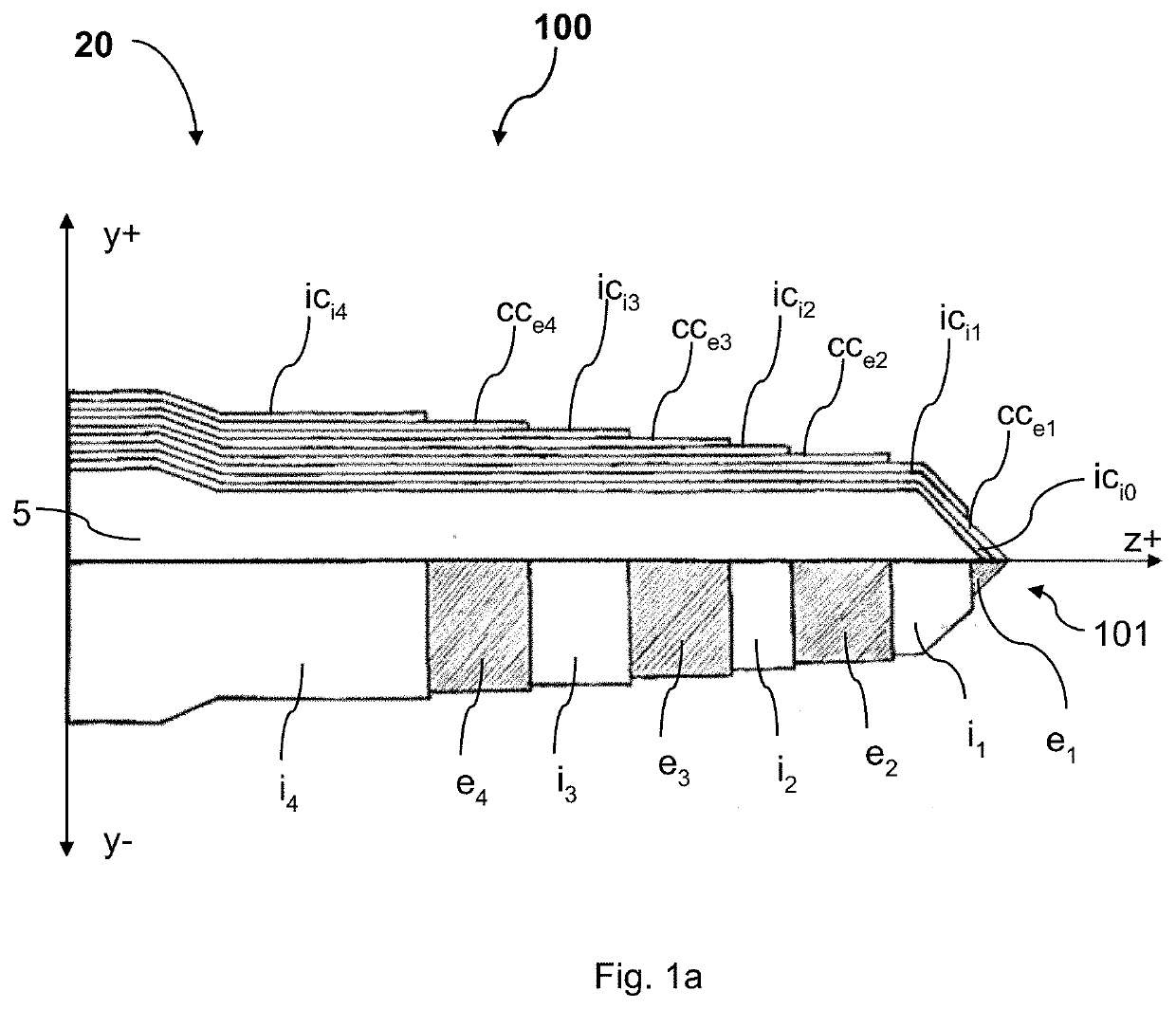
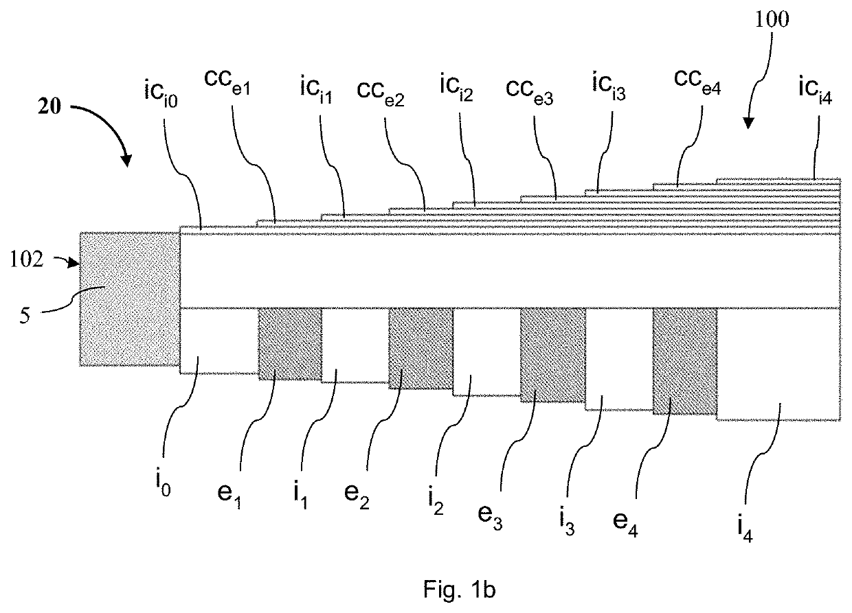
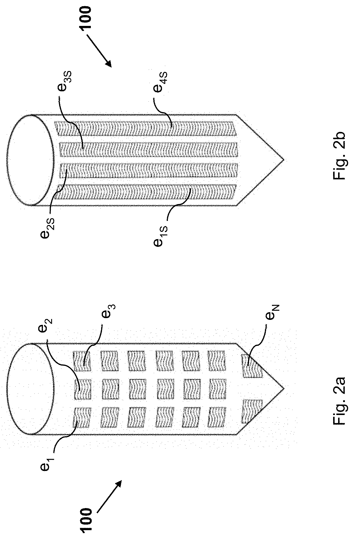
The present invention relates to an intervention device (20) for surgically intervening a target tissue of a human or animal body, comprising a penetrating body (100) arranged to be advanced into the target tissue along an advancing axis (Z+). The penetrating body (100) has an outer surface with a plurality of electrodes (e1, e2, e3, e4, . . . , eN) insulated from each other. More particularly, the penetrating body comprises a substrate base (5), a number N>1 of electrically conducting coatings (cce1, cce2, cce3, cce4, . . . , cceN) and a number M=N−1 electrically insulating coatings (ici1, ici2, ici3, . . . , iciM). A 1st electrically conducting coating (cce1) at least partially covers the substrate base (5), whereas each mth electrically insulating coating of the M electrically insulating coatings ici1, ici2, ici3, ici4, . . . , iciM) partially covers the mth electrically conducting coating of the N electrically conducting coatings (cce1, cce2, cce3, cce4, . . . ) and each nth electrically conducting coating of the N electrically conducting coatings (cce2, cce3, cce4) partially covers the (n−1)th electrically insulating coating (ici1, ici2, ici3). Thus, the outer surface of the penetrating body (100) comprises at least L=N+M sections (e1, i1, e2, i2, e3, i3, e4) alternatingly formed by the N electrically conducting coatings (cce1, cce2, cce3, cce4, . . . , cceN) and the M electrically insulating coatings (ici1, ici2, ici3, . . . , iciM). The present invention also relates to a an intervention system comprising a power supply unit and an intervention device (20; 200) as above described, wherein at least one (cce1) of the N electrically conducting coatings (cce1, cce2, cce3, cce4, . . . , cceN) of the intervention device (20; 200) is connected to the power supply unit such that it forms a cathode and at least another one (cce2, cce3, cce4) of the N electrically conducting coatings is an anode.

Description

TECHNICAL FIELD[0001]The present invention relates to an intervention device for surgically intervening a target tissue of a human or animal body according to the preamble of independent claim 1 and more particularly to an intervention device comprising a penetrating body whose outer surface is provided with a plurality of electrodes insulated from each other according to a specially engineered multi-layered configuration of electrically conducting coatings and electrically insulating coatings.[0002]Such intervention devices can be used for safely, controllably and continuously intervening a target tissue, such as bone tissue or a soft tissue.[0003]A possible application of the present invention can be, for instance, to prepare the placement of a cochlear implant, that is an electronic medical device that replaces the function of a damaged inner ear. Typically a cochlear implant comprises an internal receiver, or stimulator, which receives external signals from a speech processor an...

Claims


Application Information

Patent Timeline
IPC IPC(8): A61B34/20A61B17/16A61N1/05
CPCA61B34/20A61B17/1615A61B2017/00039A61B2034/2053A61N1/0551A61B17/16
Inventor ANSO ROMEO, JUANWEBER, STEFANGERBER, KATETHORWARTH, KERSTINCHACKO, AARATIPATSCHEIDER, JORG
Owner UNIVERSITY OF BERN
Learn More