

Coil body for an electric oil and method for producing an electronic element provided with said coil body
a technology of electric oil and coil body, which is applied in the direction of transformer/inductance coil/winding/connection, magnetic body, magnet, etc., can solve the problems of considerable additional cost and complex design, and achieve the effect of continuous reliability
- Summary
- Abstract
- Description
- Claims
- Application Information
AI Technical Summary
Benefits of technology
Problems solved by technology
Method used
Image

Examples
Embodiment Construction
[0005]The present invention is therefore based on the object of providing a coil former for an electrical coil, with which coil former it is possible to achieve improved insulation of the winding of the electrical coil. Furthermore, it is one object of the invention to provide an electronic component having such a coil former, in the case of which it is likewise possible to achieve improved insulation between a winding of the electrical coil and a coil core. In addition, it is one object of the present invention to provide a method for producing such an electronic component having a coil former according to the invention.
[0006]These objects are achieved by a coil former having the features of patent claim 1, by an electronic component having the features of patent claim 9 and by a method for producing an electronic component having the features of patent claim 12.
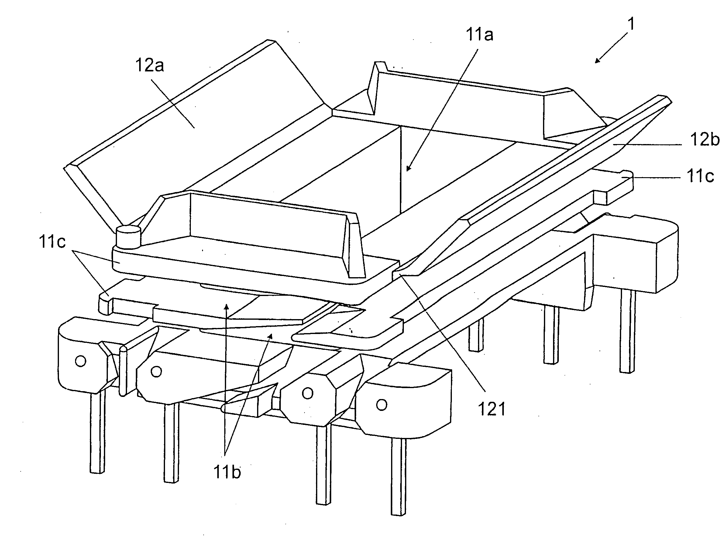
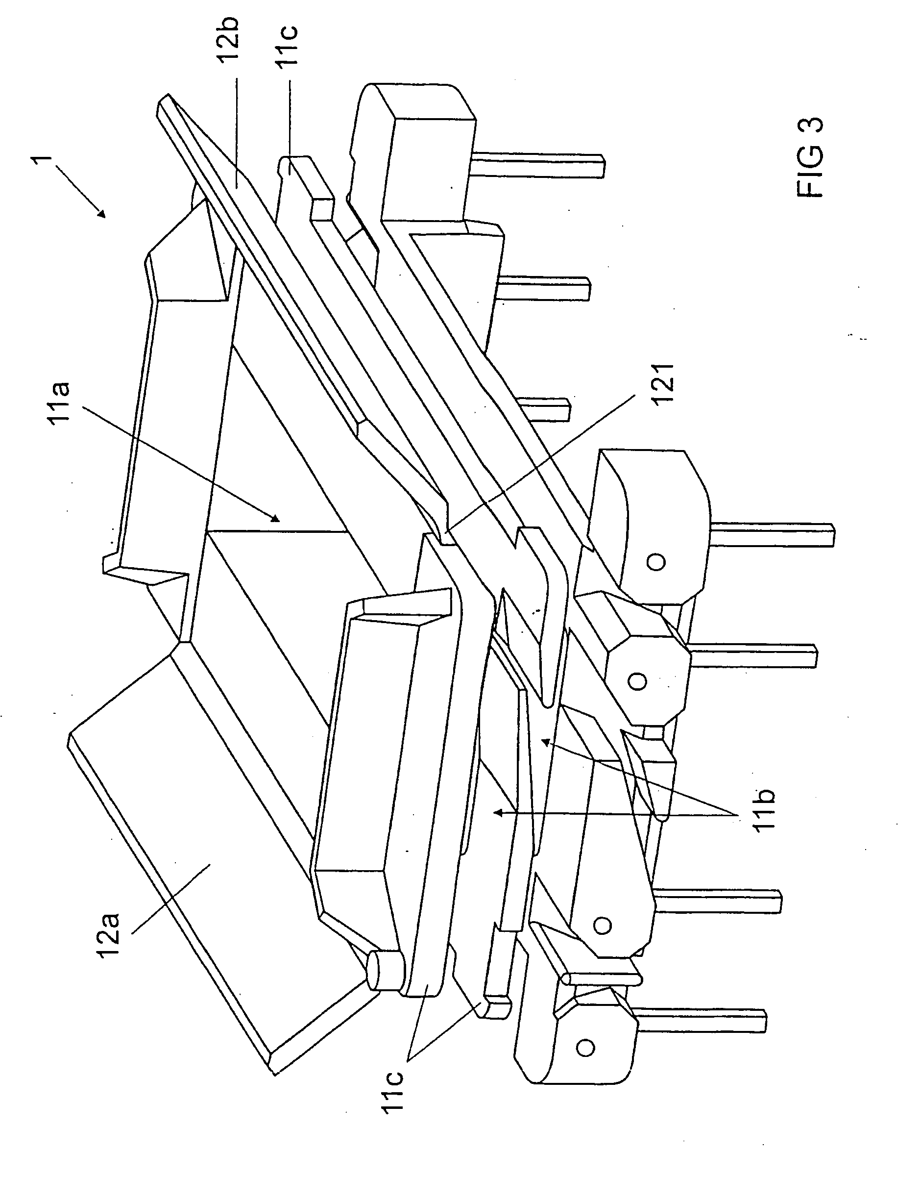
[0007]A coil former according to the invention for an electrical coil comprises a central region, which has a hollow inne...
PUM
| Property | Measurement | Unit |
|---|---|---|
| electrical | aaaaa | aaaaa |
| magnetic | aaaaa | aaaaa |
| voltage | aaaaa | aaaaa |
Abstract
Description
Claims
Application Information