
Endoscope having a sideways viewing direction
a technology of sideways and endoscopes, applied in the field of sideways viewing directions of endoscopes, can solve the problems of relatively complicated construction and involved, and achieve the effect of simple constructive measures
- Summary
- Abstract
- Description
- Claims
- Application Information
AI Technical Summary
Benefits of technology
Problems solved by technology
Method used
Image

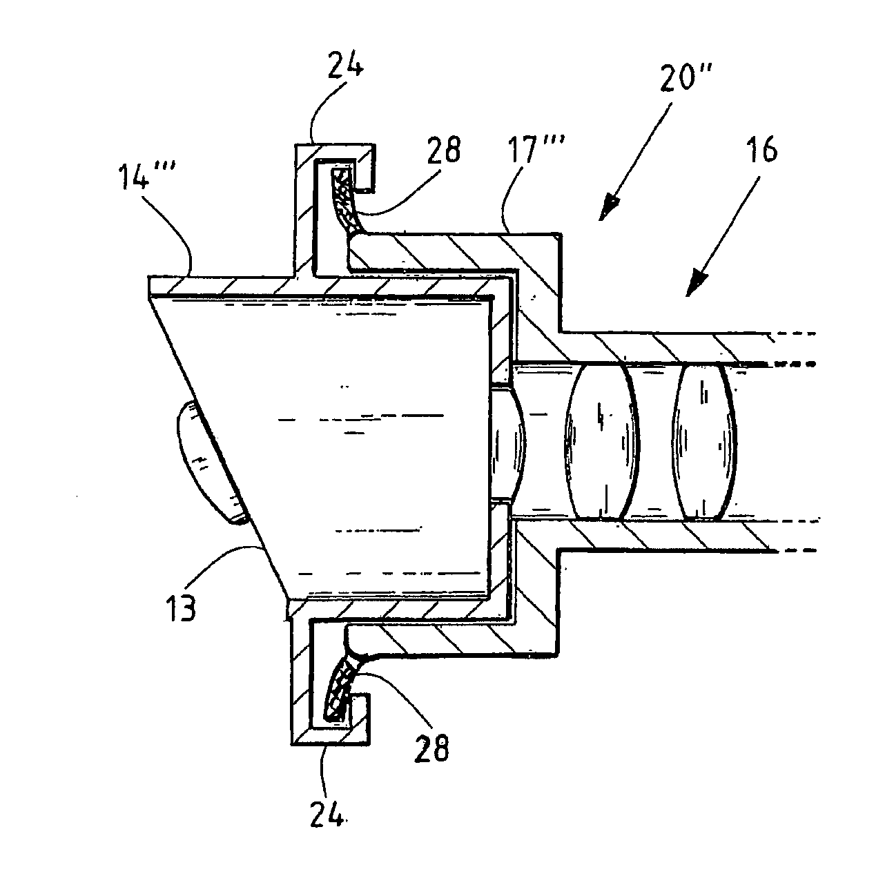
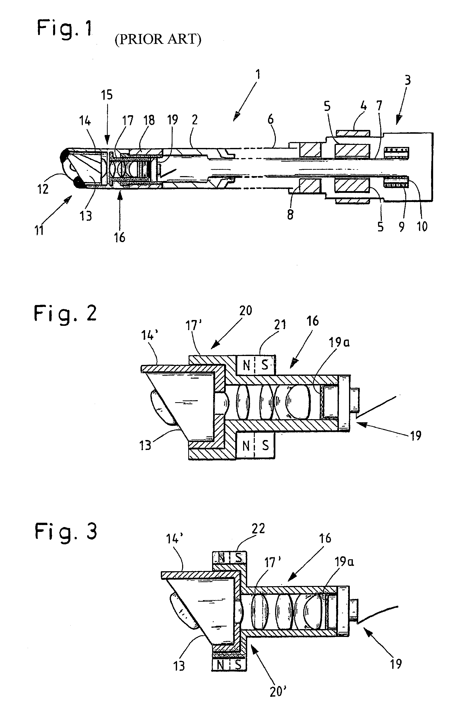
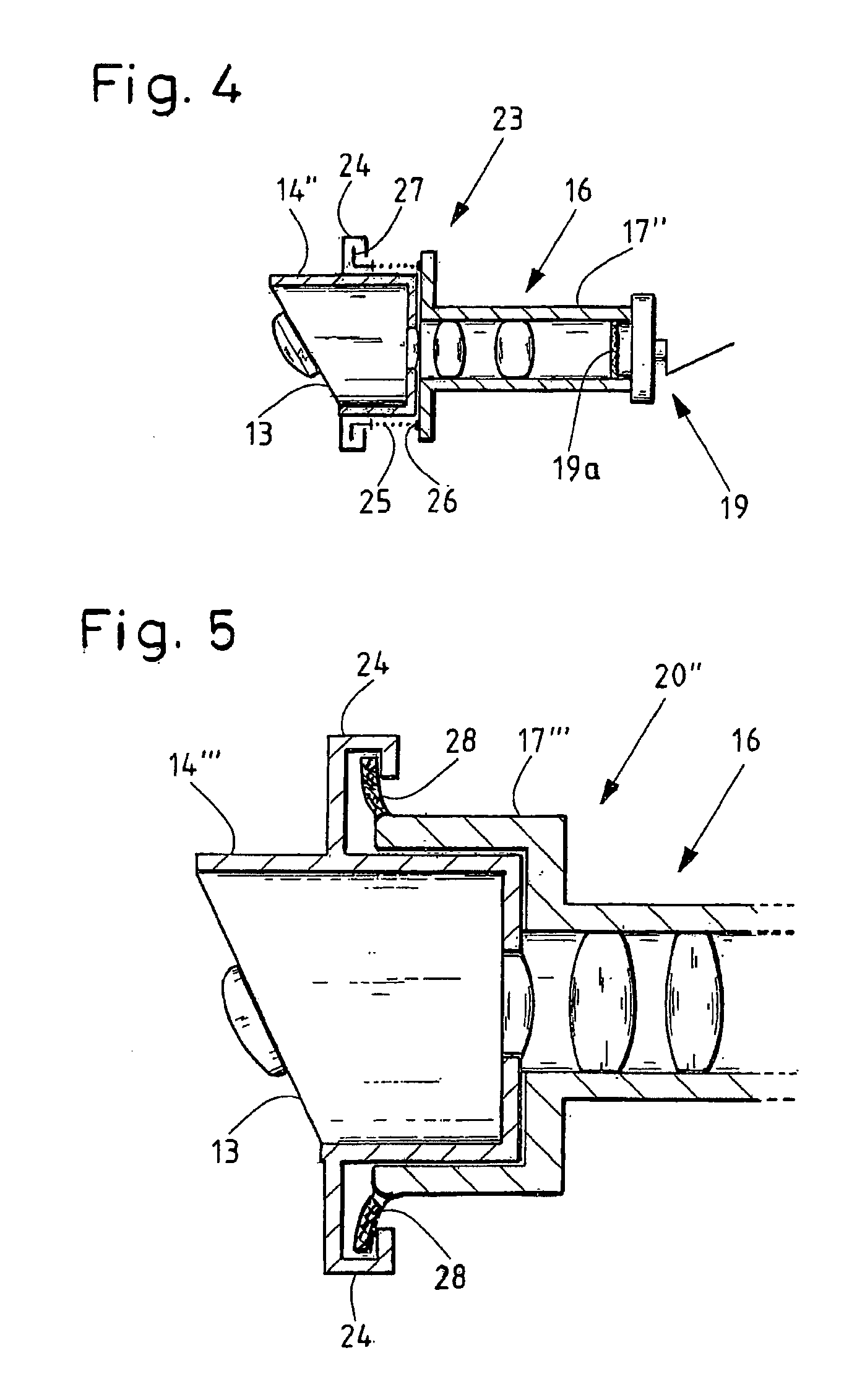
Examples
Embodiment Construction
[0033]FIG. 1 schematically represents an endoscope 1 known from the prior art. The endoscope 1 at the proximal end, shown on the right side, has a handle 3 that ends in a shaft 2. The distal end of the shaft 2 is shown on the left side in FIG. 1.
[0034]The handle 3 has a rotary ring 4 by means of which, using bar magnets 5 that are connected to an inner tube 7, the inner tube 7 can be rotated with respect to an outer tube 6, in order to change the viewing direction of the endoscope 1. The inner tube 7 is mounted in the handle 3 additionally by means of a radial bearing 8. In addition, the handle 3 comprises a pretensioning device comprised of a compression spring 9, which is pretensioned with respect to a stop 10 for the compression spring 9. The compression spring 9 ensures that the inner tube 7 is pressed, or respectively pretensioned, in the axial direction toward the distal end 11 of the shaft 2.
[0035]The shaft 2 at the distal end 11 has a window 12 that views sideways. Behind th...
PUM
 Abstract
Description
Claims
Application Information