Filter Device

a filter device and filter technology, applied in the field of filter devices, to achieve the effect of high degree of efficiency and simple constructive measures

Inactive Publication Date: 2015-12-03
MANN HUMMEL GMBH
View PDF3 Cites 1 Cited by
  • Summary
  • Abstract
  • Description
  • Claims
  • Application Information

AI Technical Summary

Benefits of technology

[0004]The invention has the object to configure a filter device having a functional part integrated in its filter element with simple constructive measures such that it has a high degree of efficiency.

Problems solved by technology

In case of radial inflow at the filter element from the exterior to the interior, the additive containers constitute an obstacle for the oil that accordingly must find a path through neighboring sections of the filter element.

Method used


Image

  • Filter Device
  • Filter Device
  • Filter Device

Examples


Embodiment Construction

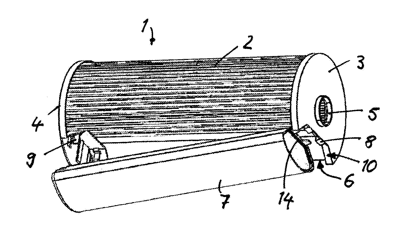
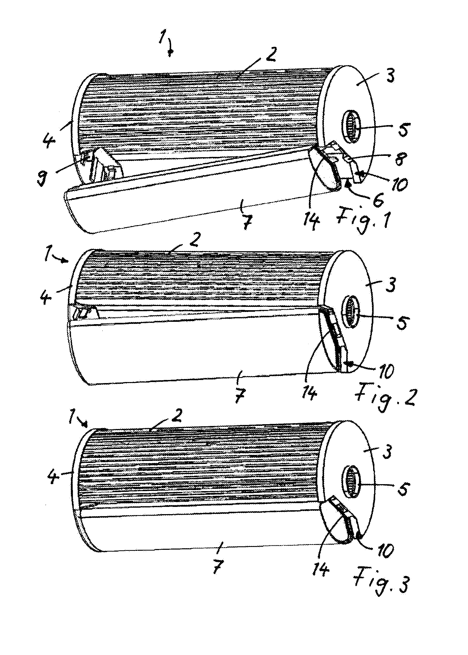
[0028]In FIGS. 1 to 3, a filter device 1 for oil filtration is illustrated. The filter device 1 comprises an annular filter element 2 that is configured as a folded filter element and comprises, distributed about the circumference, a plurality of individual paper folds. The annular filter element 2 is flowed through radially from the exterior to the interior, wherein an inwardly positioned cavity forms the clean side by means of which the clean fluid flows out axially. The annular filter element 2 is framed at both end faces by terminal discs 3, 4, wherein an outflow opening 5 is introduced into the terminal disc 3 by means of which the purified fluid is axially discharged from the inwardly positioned cavity 12 of the annular filter element 2.

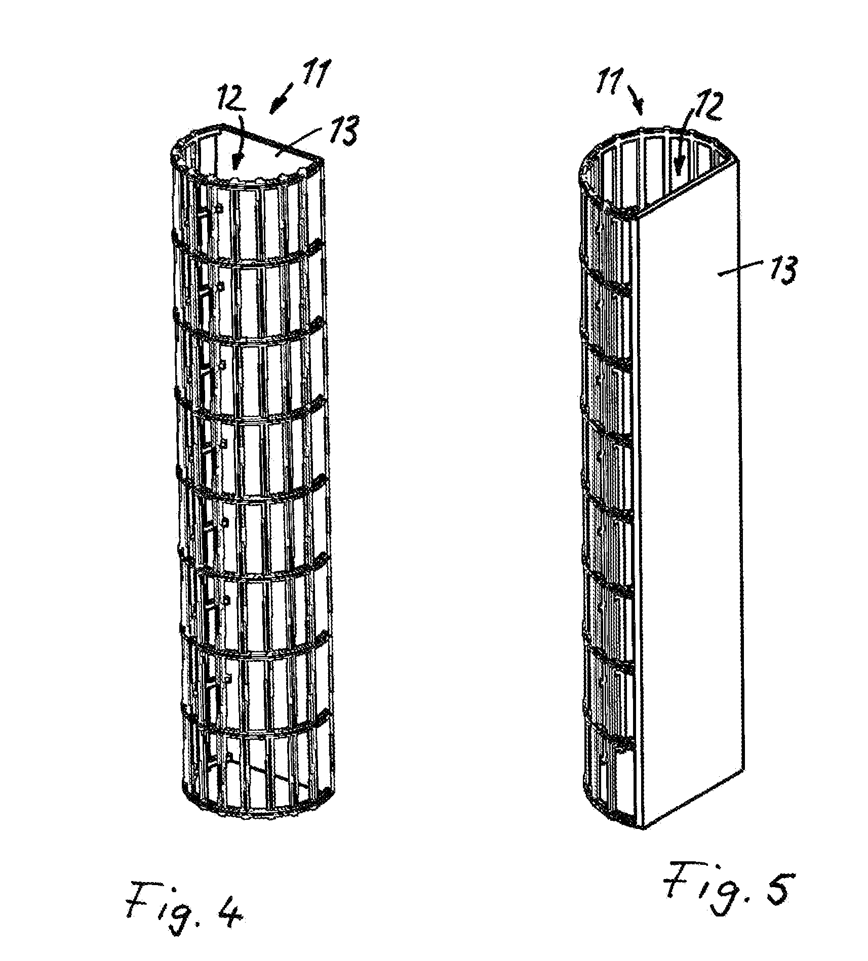
[0029]The terminal discs 3, 4 are connected fixedly with the end-face edges of the folds of the annular filter element 2. The cavity 12 in the annular filter element 2 is lined and supported by a support tube or central tube 11.

[0030]Into the f...


PUM

PropertyMeasurementUnit
outer radiusaaaaaaaaaa
shapeaaaaaaaaaa
stabilityaaaaaaaaaa

Abstract

A filter device is provided with an annular filter element. A central tube is inserted into the annular filter element so as to delimit an inwardly positioned cavity of the annular filter element. A functional part is inserted into the annular filter element and extends parallel to a longitudinal axis of the annular filter element, wherein the functional part is arranged in radial direction of the annular filter element outward of the central tube. The functional part has a radial inwardly positioned wall facing the central tube. The central tube has a facing wall that is facing the radial inwardly positioned wall of the functional part. The radial inwardly positioned wall of the functional part is positioned parallel to or concentric to the facing wall of the central tube.

Description

CROSS-REFERENCE TO RELATED APPLICATIONS[0001]This application is a continuation application of international application No. PCT / EP2013 / 075898 having an international filing date of 9 Dec. 2013 and designating the United States, the International Application claiming a priority date of 11 Jan. 2013, based on prior filed German patent application No. 10 2013 000 337.7, the entire contents of the aforesaid international application and the aforesaid German patent application being incorporated herein by referenceBACKGROUND OF THE INVENTION[0002]The invention concerns a filter device, in particular liquid filter, comprising an annular filter element and a functional part insertable into the filter element and extending parallel to the longitudinal axis of the filter element.[0003]U.S. Pat. No. 3,749,247 discloses a filter device for oil filtration that comprises a folded annularly configured filter element which is flowed through by the oil to be purified in radial direction. In order ...

Claims


Application Information

Patent Timeline
Patent Type & Authority Applications(United States)
IPC IPC(8): B01D29/13
CPCB01D29/13B01D37/025B01D29/21B01D2201/0415B01D2201/291B01D2201/4084B01D2239/04
Inventor GOHL, PAMELAFAISST, MARCOJOKSCHAS, GUENTERTRAUTMANN, PIUS
Owner MANN HUMMEL GMBH
Why Eureka
Try Eureka