
Display device and method of controlling the same

a display device and liquid crystal technology, applied in the field of liquid crystal display, can solve the problems of inability to display luminance images on display devices, and significant reduction in the brightness of the image output of the display device compared to the original imag

Active Publication Date: 2018-10-02
SAMSUNG ELECTRONICS CO LTD
View PDF31 Cites 4 Cited by
  • Summary
  • Abstract
  • Description
  • Claims
  • Application Information

AI Technical Summary

Benefits of technology

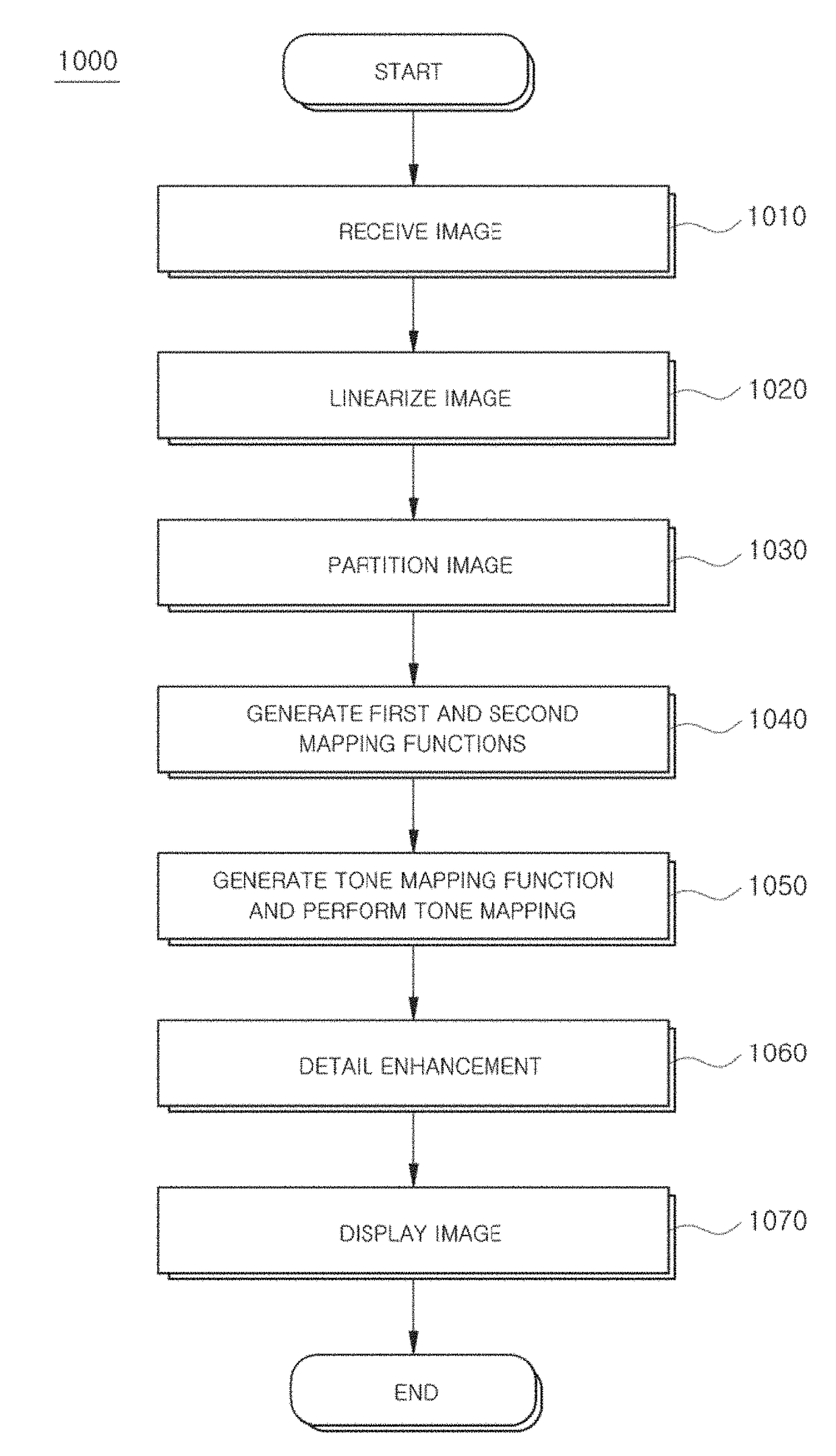
The patent describes a display device and method that can show an image without changing its brightness, and also display information in the brightest parts of the image without distortion. This is achieved by using different tone mapping functions for different parts of the image, so that the image looks good on both low and high luminance regions.

Problems solved by technology

However, according to the method in which the entire dynamic range of the high dynamic range image is compressed, there is a problem in that brightness of the image output from the display device significantly decreases compared to an original image.
Also, according to the method in which the high dynamic range image is directly displayed on the display device having a low dynamic range, there is a problem in that an image of a luminance, which is unable to be displayed on the display device, is not displayed.

Method used


Image

  • Display device and method of controlling the same
  • Display device and method of controlling the same
  • Display device and method of controlling the same

Examples


Embodiment Construction

[0070]Reference will now be made in detail to the embodiments, examples of which are illustrated in the accompanying drawings, wherein like reference numerals refer to the like elements throughout. The embodiments are described below by referring to the figures.

[0071]Embodiments described in this specification and configurations illustrated in drawings are only exemplary examples of the disclosed embodiments. The embodiments cover various modifications that can substitute for the embodiments herein and drawings at the time of filing of this application.

[0072]Hereinafter, an embodiment will be described in detail with reference to the accompanying drawings.

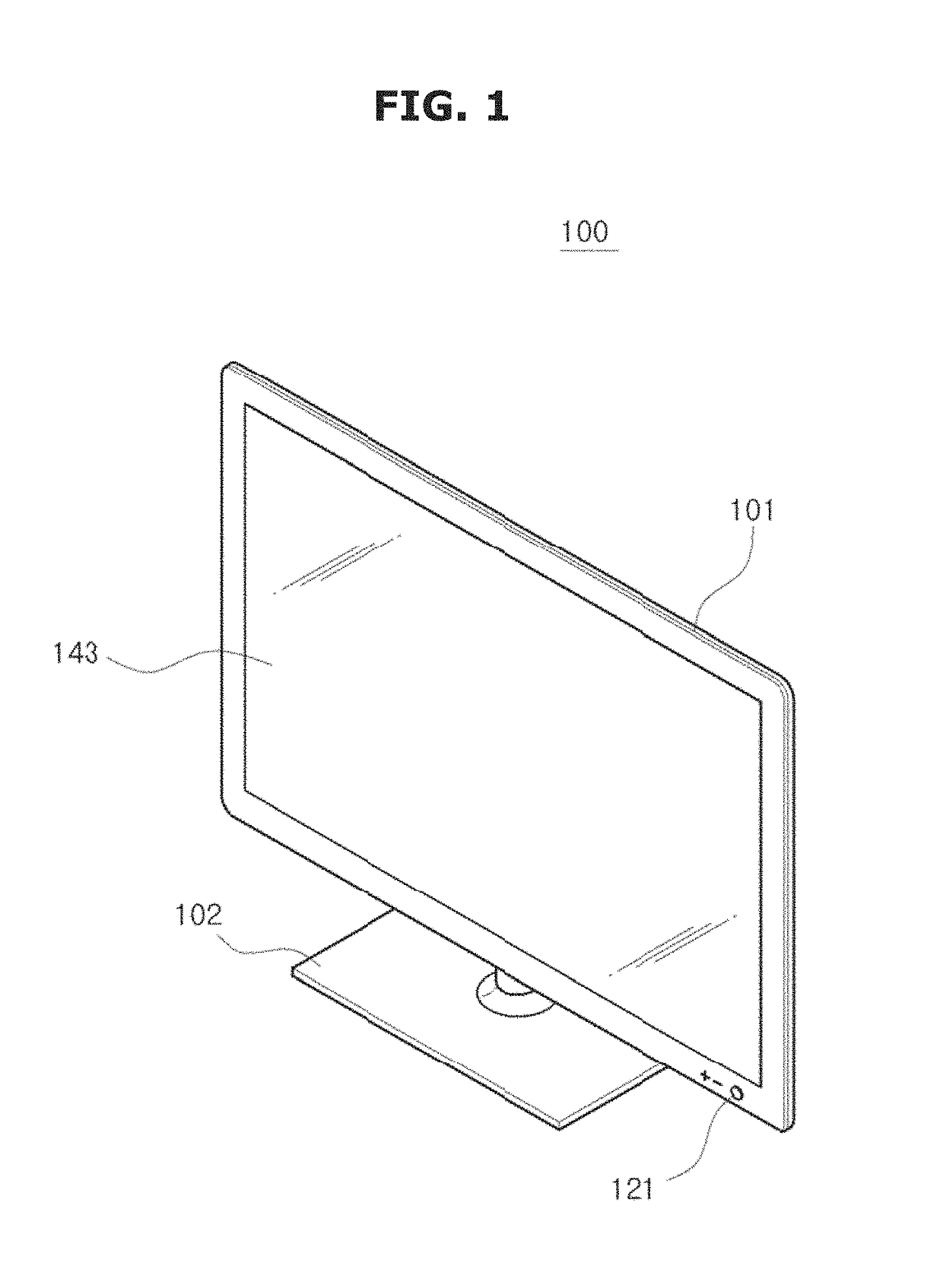
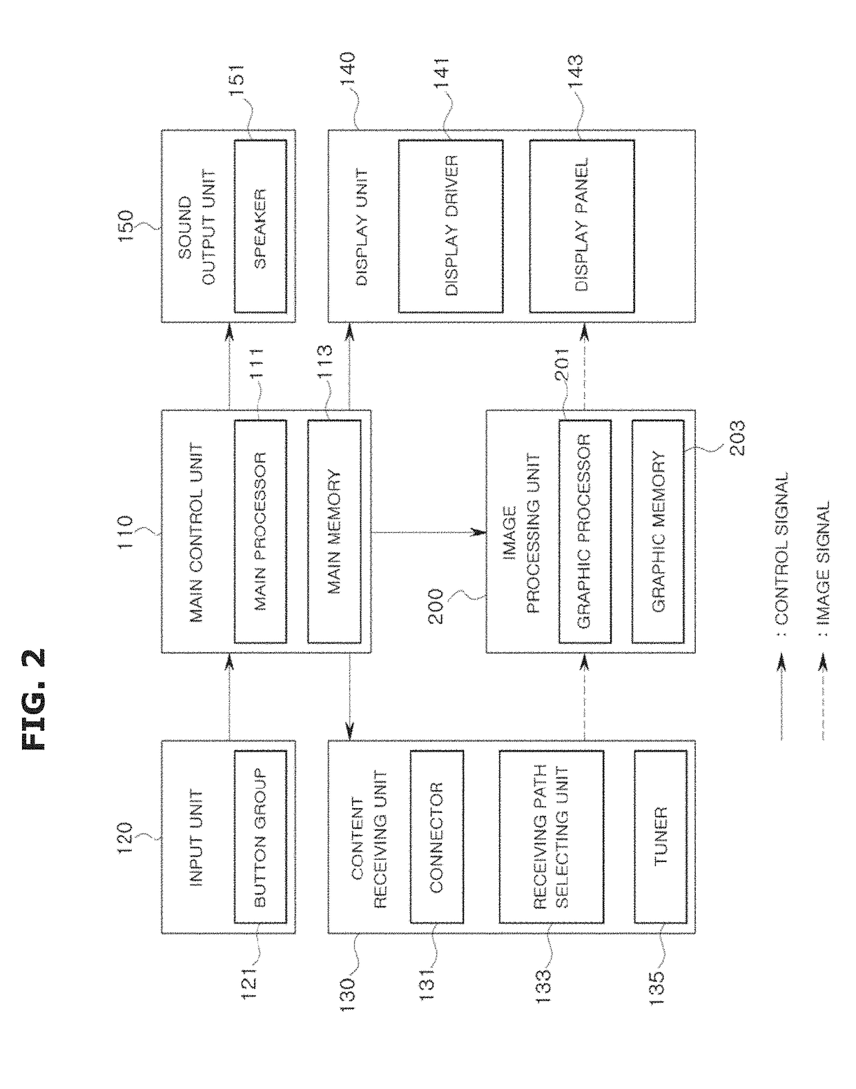
[0073]FIG. 1 illustrates an exterior of a display device according to an embodiment. FIG. 2 illustrates a control configuration of a display device according to an embodiment.

[0074]A display device 100 is a device that may process an image signal received from the outside and visually display the processed image. Hereinafter, a cas...


PUM


Abstract

A display device, including a content receiving unit configured to receive a high dynamic range image, an image processing unit configured to detect a first region whose luminance value is equal to or greater than a reference luminance value within the high dynamic range image and perform tone mapping on an image of the first region based on feature information of the image of the first region, and a display unit configured to display a low dynamic range image on which the tone mapping is performed.

Description

CROSS-REFERENCE TO RELATED APPLICATIONS[0001]This application claims the benefit of Korean Patent Application Nos. 10-2014-0134135 and 10-2015-0024271, filed on Oct. 6, 2014 and Feb. 17, 2015, respectively, in the Korean Intellectual Property Office, the disclosures of which are incorporated herein by reference.BACKGROUND[0002]1. Field[0003]Embodiments relate to a liquid crystal display with a heat generation unit to preheat a liquid crystal display panel and a driving method thereof.[0004]2. Description of the Related Art[0005]In general, a luminance of the actual world is known to have a dynamic range of 100,000,000:1. Also, a contrast range that can be distinguished by a human's eyes, that is, a dynamic range of a human's eyes, is known to be about 1,000:1 to 10,000:1. A dynamic range of cameras according to the newest technology is known to be about 10,000:1.[0006]On the other hand, a liquid crystal display panel, a plasma display panel, an organic light emitting diode panel, an...

Claims


Application Information

Patent Timeline
Patent Type & Authority Patents(United States)
IPC IPC(8): G06T5/00G09G3/34G09G3/36G09G5/00
CPCG09G3/3413G09G3/3607G09G5/003G09G2320/0233G09G2360/16G09G2320/0666G09G2320/0673G09G2340/0428G09G2340/06G09G2320/064G09G5/10H04N5/45H04N5/57H04N9/77H04N21/422H04N21/42204H04N21/426G06T5/40G06T5/92G06T5/94
Inventor HAN, SEUNG-HOONSEO, GUI WONLEE, SANG WOOKKIM, CHANG WON
Owner SAMSUNG ELECTRONICS CO LTD
Learn More